The more the throttling action by the valve, the higher the energy dissipation. In continuous manufacturing processes, the cost of the energy consumed by a particular pump motor is normally far in excess of the capital cost of the required variable frequency drive, so the payback period on variable frequency drives is short.
Increased energy efficiency can also be realized by using regenerative variable frequency drives that pump the braking energy back into the supply network rather than dissipating this energy in braking resistors or in mechanical brake systems.
Increased energy efficiency can also be realized by using regenerative variable frequency drives that pump the braking energy back into the supply network rather than dissipating this energy in braking resistors or in mechanical brake systems.
The reliability of power electronic systems, including variable frequency drives, depends on certain environmental limits being maintained. These limits relate to maintaining the efficient extraction of the heat due to switching losses so that no single component within the VFD is subjected to an over-temperature condition. Over-temperatures will result in the reduction of the expected life of the components. As the bulk of variable frequency drives are air-cooled, the quality and quantity of the cooling air flow need to be maintained.
History has shown that electrical VFDs using power electronics have not been that network-friendly. Either the VFD has operated at a poor power factor that decreases with a decrease of motor speed or it has injected large harmonic currents back into the supply network. All power electronic systems inject harmonic currents into the network due to their non-linearity. The effects of the harmonics that are injected into the network include overheating of transformers, cables, motors, alternators and capacitors; and maloperation of protection relays and other instrumentation that were not designed with an insensitivity to harmonics in the supply. Thus, some form of harmonic reduction is required. This can be implemented through structural modification within the VFD system or through external filtering.
Mechanical VFDs include the following subtypes:
- Variable pitch drive – a belt and pulley drive where the pitch diameter of one or both pulleys is adjustable, giving a multi ratio and hence a variable output speed.
- Traction drive – the diameter of the contact path of two mating metal rollers is adjustable, giving a multi ratio hence a variable output speed.
- Hydraulic hydrostatic drive - a positive displacement hydraulic pump and motor where the volumetric fluid output of the pump is varied through valves or by varying the displacement.
- Hydraulic hydrodynamic drive or fluid coupling – two impellors coupled together with hydraulic fluid. By varying the volume of the fluid the degree of coupling from primary to output can be varied and therefore variable speed obtained.
- Hydraulic hydro viscous drive – a number of discs on the input shaft pressed against a corresponding number of discs on the output shaft. There is a film of oil between the discs. By varying the pressure squeezing the discs together the torque transfer can be varied hence realizing variable speed operation.
Manufacturers of VFD technology can offer end users an extraordinary level of reliability, which can be compromised if end users neglect to embrace a lifecycle approach that includes the VFD manufacturer from cradle (design) to grave (replacement). During the design stages, performance and selection criteria obviously merit the involvement of the manufacturer, but end users need to adjust their readiness to take over full responsibility soon after completion of the commissioning phase.
Manufacturers that recognize the importance of preventive maintenance can provide a valuable role in setting up a comprehensive preventive maintenance schedule that spans the life of the basic VFD. During the operational life of the VFD, the manufacturers can advise on basic measures to maintain the high levels of reliability of which VFDs are capable. These include keeping the VFD clean, cool, dry and the connections tight. Their importance and impact cannot be over emphasized.
Manufacturers that recognize the importance of preventive maintenance can provide a valuable role in setting up a comprehensive preventive maintenance schedule that spans the life of the basic VFD. During the operational life of the VFD, the manufacturers can advise on basic measures to maintain the high levels of reliability of which VFDs are capable. These include keeping the VFD clean, cool, dry and the connections tight. Their importance and impact cannot be over emphasized.
Start with all the advantages of VVVF VFDs:
- Use "standard", low-cost, induction motors. Explosion-proof motors and other special construction is widely available. Brushes, commutators, or special "permanent-magnet' rotors are not required.
- High-input displacement power factor (about 95%), for lower-cost power.
- Some inherent ability to "hold back" loads through regeneration without extra hardware.
- High-speed capability (6,000 RPM is easily attainable).
- Closed-loop speed regulation to 0.01%.
- High-dynamic response of greater than 50 radians/second.
- Smooth low-speed operation, even under changing loads.
- High breakaway torque (150% or even 200% is common).
- Linear torque control for positioning or tension.
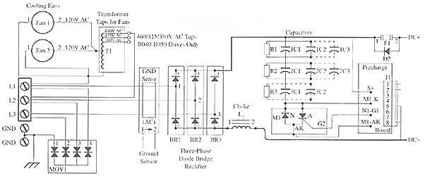
One can get a better idea of how the diodes in the rectifier and the devices in the filter and regulator sections of a circuit all work together when one sees a complete electronic circuit for an operational system. Following Figure shows the electrical diagram of a VFD that is commonly used in industrial applications. From this diagram notice that the VFD circuit uses three phase power source voltage, so a three phase full-wave bridge rectifier is used. Keep in mind that it's encapsulated so one doesn't see each of the diodes. Rather one would find the terminals for the three input terminals and the two dc output terminals.


VFD Control Features
- Open loop vector control variable frequency drive
- Speed or torque control variable frequency drive
- Speed reference input: 0-10V, 0-20mA, 4-20mA, (-10 to +10V SM-I/O Lite option)
- 4 digital inputs- World (enable, run forward, run reverse, local/remote)- USA (not stop, run, jog, local/remote)
- VFD switching frequency: 3 (default) – 6 – 12– 18 kHz
- VFD Output frequency 0 to 1500Hz
- VFD Accelerate and Decelerate ramps (linear and S type)
- Positive logic control
- Serial communication - Modbus RTU RS485 via RJ45 connector- Baud rate 4800, 9600, 19200or 38400 bits per second
- DC injection braking as standard in the VFD
- Dynamic braking transistor as standard in the VFD
- Dynamic motor flux V/Hz for energy saving
- Quadratic motor flux V/Hz for fan and pump optimization
While vector VFDs offer many advantages, they have a few limitations, too. Vector VFD represents the step forward in performance that many applications have needed to enjoy the advantages of AC technology. It is clear we will see them widely used in new applications. They can also be an alternative to existing mechanical and electrical VFDs.
When evaluating systems for variable frequency drives, we need to keep in mind that there are different types of loads, each with different characteristics. They are:
- variable torque loads like fans and pumps,
- constant torque loads like conveyors and positive displacement or reciprocating pumps, and
- constant horsepower loads like grinders and winding machines.
Variable Frequency Drives (VFD, aka variable speed drive - VSD, Adjustable Speed Drive - ASD) have been available for use with a wide range of applications for over 20 years. These applications include single motor driven pumps, fans and compressors, as well as highly sophisticated multi-drive machines.
The variable voltage input (VVI) VFD is the technology that was used in some of the earliest VFD. Since these earlier VFDs did not have microprocessor chips to establish the transistor VFDs signals, they used existing technology such as oscillators. The diagrams below shows a block diagram of this type of VFD and a typical waveform of the output.
Featured Articles
Variable Frequency Drive Harmonics and ...
A discussion of the benefits of variable frequency drives often leads to a question regarding electrical harmonic distortion ...
Three phase inverters
 In the variable frequency drive rectifier paper, it explains how to go from three phase alternating current voltage to a direct ...
 In the variable frequency drive rectifier paper, it explains how to go from three phase alternating current voltage to a direct ...
Variable frequency drive Advantages & ...
VFDs are good for variable speed, in a water pump this is used to maintain a steady pressure, they will smooth out variances in ...
Variable frequency drive Rectifier
 To understand variable frequency drive (VFD) better, it's necessary to explain some of the main parts of the variable frequency ...
 To understand variable frequency drive (VFD) better, it's necessary to explain some of the main parts of the variable frequency ...
VFD controlled Induction motor ...
 This paper presents a procedure to measure the efficiency on an induction motor fed by a VFD by the all operation range to speed ...
 This paper presents a procedure to measure the efficiency on an induction motor fed by a VFD by the all operation range to speed ...
VFD manufacturers
