Home » Wiki
The Total Harmonic Current Distortion (THDi) of a variable frequency drive (VFD) depends on the pulse assys. Standard for the VFD is 6 pulse, with a THDi at or about 40%, +/- 5%. With 12 and 18 pulse, this is of course reduced. These levels are also induced by source impedance, that being the line supply and distortions within it. VFD also employs a DC bus line reactor to help with harmonic distortions. This allows distances between the motor and drive of 1000 plus feet without aid. The distances between the motor and drive can go up to 500 feet unaided. The VFD with no DC link reactor has a THD(i) of 70%, =/- 5%. With any of these, significant reductions in harmonic generation is accomplished with the addition of an output RFI filter, which then enhances distance capability between the motor and drive to 1,000 feet unaided, and meets the stringent European RFI requirements.
The evolution of the power semiconductors have led to the creation of more efficient, but also faster, electronic switches. The high switching frequency of the IGBT transistors employed in modern variable frequency drives (VFD) bring about some undesirable effects, such as the increase of electromagnetic emission and the possibility of voltage peaks, as well as high dV/dt ratios (time derivative of the voltage, that is, rate of electrical potential rise), occurrence at the variable frequency drive fed motor terminals. Depending on the control characteristics (gate resistors, capacitors, command voltages, etc.) and the PWM adopted, when induction motors are fed by VFDs, those pulses combined with the impedances of both the cable and the motor may cause repetitive overvoltages on the motor terminals. This pulse train may degrade the motor insulation system and may hence reduce the motor lifetime.
The cable and the motor can be considered a resonant circuit, which is excited by the variable frequency drive rectangular pulses. When the values of R, L and C are such that the peak voltage exceeds the supply voltage (VDC ≈ 1.41 Vin), the circuit response to this excitation is a so called "overshoot". The overshoots affect especially the interturn insulation of random windings and depend on several factors: rise time of the voltage pulse, cable length and type, minimum time between successive pulses, switching frequency and multi-motor operation.
The cable and the motor can be considered a resonant circuit, which is excited by the variable frequency drive rectangular pulses. When the values of R, L and C are such that the peak voltage exceeds the supply voltage (VDC ≈ 1.41 Vin), the circuit response to this excitation is a so called "overshoot". The overshoots affect especially the interturn insulation of random windings and depend on several factors: rise time of the voltage pulse, cable length and type, minimum time between successive pulses, switching frequency and multi-motor operation.
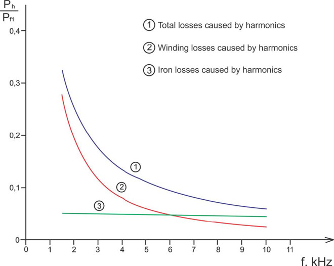
A discussion of the benefits of variable frequency drives often leads to a question regarding electrical harmonic distortion problems. When evaluating variable frequency drives, it is important to understand how harmonics are provided and the circumstances under which harmonics are harmful.
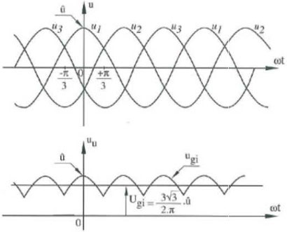
Variable frequency drives draw current from the line only when the line voltage is greater than the DC Bus voltage inside the VFD. This occurs only near the peaks of the sine wave. As a result, all of the current is drawn in short intervals (i.e., at higher frequencies). Variation in variable frequency drive design affects the harmonics produced. For example, variable frequency drives equipped with DC link inductors produce different levels of harmonics than similar variable frequency drives without DC link inductors. The variable frequency drive with active front end utilizing transistors in the rectifier section have much lower harmonic levels than variable frequency drives using diodes or silicon controlled rectifiers (SCRs).
Variable frequency drives draw current from the line only when the line voltage is greater than the DC Bus voltage inside the VFD. This occurs only near the peaks of the sine wave. As a result, all of the current is drawn in short intervals (i.e., at higher frequencies). Variation in variable frequency drive design affects the harmonics produced. For example, variable frequency drives equipped with DC link inductors produce different levels of harmonics than similar variable frequency drives without DC link inductors. The variable frequency drive with active front end utilizing transistors in the rectifier section have much lower harmonic levels than variable frequency drives using diodes or silicon controlled rectifiers (SCRs).
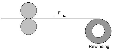
There are two ways in tension control, one way is to control the output torque of the motor, the other way is to control the motor speed. Variable frequency drive (VFD) open-loop control mode is complied with the first way, which doesn't need tension feedback. The term, "open-loop", means there is no tension feedback signal to the VFD, the VFD control the output frequency or torque to achieve the control purpose, and with no relation whether there is an encoder or not. Torque control mode means the VFD controls the motor torque instead of the frequency, the output frequency is automatically changed according to the speed.


The induction motor can be made easily and with that the price is rather low compared with other technologies. The induction motor doesn't use a combustion process to deliver power so there is no need to (re)fuel or air. The cooling can be integrated so that the induction motor can work in a hermetically sealed environment for instance under water. The induction motor has a high power to weight ratio. Another advantage is the high start torque so that starting under load is possible. Since the development of variable frequency drives and vector control systems, this induction motor is also easy to control in speed and torque. This gave a lot of opportunities in automation processes. In the following paper, the principle, characteristics and control of the induction are explained.
In this paper a description is given how to set up the parameters for use the motor with a standard induction motor. Lot of this is based on the operating instructions manual that is available from Gozuk. This guide gives an explanation of how to set up the variable frequency drive (VFD) for any induction motor. The slide adaptations that are made in this setup description are because at a University the variable frequency drive is used for a specific motor and this made it possible to narrow and/or specify the original manual where the information to vague and include extra notes based on the problems that occurred during the installation of the variable frequency drive to the motor at the university. The first part of the description handles about the hardware configuration, first the fixed hardware and second the set up of the motor and control items. Where needed pictures are included to explain the process. The second part of this setup description gives a look on the different parameters in the variable frequency drive; what they mean, how to adapt them and what the possibilities are. This setting up description doesn't include actual experiments, just how the configurations are made before beginning the experiments.
The major advantage of DTC is fast torque response. The major disadvantage of DTC is the large current harmonic or torque ripple of the original algorithm. That also indicates the reason that why in the research area people keep working on improving algorithms or those estimators to reduce torque ripple even in the recent APEC 2014. Also, this can be proved by the improvements to DTC patents. However, due to these improvements, the DTC used in ABB variable frequency drive is as good as Field Oriented Control (FOC). This explains why people use DTC don't think the torque ripple is high.
In the variable frequency drive rectifier paper, it explains how to go from three phase alternating current voltage to a direct current voltage by means of a rectifying circuit. The three phase bridge inverter with six diodes seemed a good starting point to convert AC to DC. In this paper the opposite process is described. When a DC source (voltage or current) is available an inverter can be used to convert the energy to an AC source. When the source is a direct current source a current source inverter is needed, when it is a DC voltage source a constant or variable voltage source inverter can be used. The direct current source has not so many applications so it will not be described.


Placing a proper size variable frequency drive near motor instead of in central control panels allows for much faster servicing. It also accelerates initial installations, so the system is productive sooner. Decentralized intelligence, the practice of putting motion control into VFDs instead of in central PLCs, results in simpler PLC programs that interface with smart VFDs rather than complicated programs that are large and difficult to handle.
Be sure to check application torque performance requirements (both steady state and dynamic) and select the appropriate VFD - either V/F, sensorless vector, full vector, servo, and so on. Don't forget to consider the application's environmental requirements. If a higher enclosure integrity is required (such as NEMA 12/IP55 or NEMA 4X/ IP66), some specified VFDs can provide this out of the box while others will have to be "enclosed" in a separate host enclosure to obtain these levels.
Be sure to check application torque performance requirements (both steady state and dynamic) and select the appropriate VFD - either V/F, sensorless vector, full vector, servo, and so on. Don't forget to consider the application's environmental requirements. If a higher enclosure integrity is required (such as NEMA 12/IP55 or NEMA 4X/ IP66), some specified VFDs can provide this out of the box while others will have to be "enclosed" in a separate host enclosure to obtain these levels.
This sort of performance is available only in conjunction with a high-performance flux-vector variable frequency drive controller. Three variable frequency drive controllers up to the task are:
a.) Gozuk EDS AC flux-vector variable frequency drive controller.
b.) ABB ACS-800 AC drive controller with direct-torque control.
c.) Emerson - Control Techniques "Uni-Drive" in full flux-vector mode.
a.) Gozuk EDS AC flux-vector variable frequency drive controller.
b.) ABB ACS-800 AC drive controller with direct-torque control.
c.) Emerson - Control Techniques "Uni-Drive" in full flux-vector mode.
Generally, an AC motor can produce 100% of the motor rated torque at any speed, if applied on a good quality variable frequency drive (VFD). If 100% torque is required for long periods at zero or very low speed (below, say 5Hz or 1/10 of base speed) then a speed feedback device (tach, encoder, resolver) will probably be needed. Also, auxiliary cooling or other measures will be necessary to prevent motor thermal failure.
The full-load rated torque of a 7.5Hp 4-pole motor with a base speed of 1775 RPM is 22.5 ft.-lbs. Any good quality VFD will allow you to generate this torque at any speed between about 20RPM and 1750RPM. You could also select a 5Hp 1175RPM motor and drive, and overspeed the motor to 90Hz to reach 1750RPM on extraction - the lack of available torque at high speed is not a hindrance in this application.
The full-load rated torque of a 7.5Hp 4-pole motor with a base speed of 1775 RPM is 22.5 ft.-lbs. Any good quality VFD will allow you to generate this torque at any speed between about 20RPM and 1750RPM. You could also select a 5Hp 1175RPM motor and drive, and overspeed the motor to 90Hz to reach 1750RPM on extraction - the lack of available torque at high speed is not a hindrance in this application.
The variable frequency drive cable doesn't do much for motor insulation, it is for motor bearing protection (I won't speak to the effectiveness of such cable). Many years of experience says that if you are going to spend the money on the VFD cable, have it installed properly. Regardless, always attempt to keep the cable distance from the VFD to motor short as possible (30m or less). If it gets longer, discuss with your motor and VFD manufacturer. There are many differences between both VFD and motor designs, let alone the system voltage used.
Featured Articles
Variable Frequency Drive Harmonics and ...
A discussion of the benefits of variable frequency drives often leads to a question regarding electrical harmonic distortion ...
Three phase inverters
 In the variable frequency drive rectifier paper, it explains how to go from three phase alternating current voltage to a direct ...
 In the variable frequency drive rectifier paper, it explains how to go from three phase alternating current voltage to a direct ...
Variable frequency drive Advantages & ...
VFDs are good for variable speed, in a water pump this is used to maintain a steady pressure, they will smooth out variances in ...
Variable frequency drive Rectifier
 To understand variable frequency drive (VFD) better, it's necessary to explain some of the main parts of the variable frequency ...
 To understand variable frequency drive (VFD) better, it's necessary to explain some of the main parts of the variable frequency ...
VFD controlled Induction motor ...
 This paper presents a procedure to measure the efficiency on an induction motor fed by a VFD by the all operation range to speed ...
 This paper presents a procedure to measure the efficiency on an induction motor fed by a VFD by the all operation range to speed ...
VFD manufacturers
