If you are running the system with variable frequency drive then you should precharge the tank to 65% of cutoff pressure. If you have a traditional booster system running with pressure switch the tank pre charge should be 2 psi below the cut in pressure. If you will charge the tank 50% of maximum pressure instead of 65% that means your tank pre charge is less. Your pump start & stop will be more. Which is not correct .You are consuming more power, & also pump life will not be more & may need maintenance faster.
assuming the pump is properly sized, the life cycle is more often related to starts and stops. The more frequent the start/stop the shorter the pump life. The adverse effect of repeated starting can be lessened by using a soft starter or variable frequency drive to bring the pump on line slower that the direct on-line start. A variable frequency drive can also allow for fine tuning the system and adapting to changing system conditions such as a widely variable suction head or changes in viscosity.
The number of starts & time between starts too should be considered when selecting starters. That's yet another issue. Larger motors may have limits on how many full-speed starts can be performed in a particular time frame. There are several ways to deal with this. One is to have a PLC refuse to start if the number of starts in the time frame has been exceeded. Using a soft start or a VFD can extend the number allotted. On very large motors, temperature sensors can be embedded in the windings, and you can simply refuse start if the winding temperature is too high.
In general, if the electrical engineer does not fully understand the operation variables of the pumping operation, he will not be able to design a proper operation and protection gear.
I highly recommend that you read some literature such as Pumping station design which includes a chapter on electrical design considerations and variable frequency drive (VFD) applications. This is one of the best manuals in this domain, also many pump manufacturers have their own references for such a topic.
I highly recommend that you read some literature such as Pumping station design which includes a chapter on electrical design considerations and variable frequency drive (VFD) applications. This is one of the best manuals in this domain, also many pump manufacturers have their own references for such a topic.
When you buy any pump and variable frequency drive (VFD), EXCLUDING a fire pump, you can pick whatever brand of VFD you want with whatever features you want based on known existing problems or a desire to help eliminate future problems. The only shaft that comes with that package is the one in the pump casing.
When you buy a VFD fire pump controller you get whatever the manufacturer had it listed with. Those packages come with two shafts - the one in the pump and the one you got with a standard listed VFD fire pump controller.
When you buy a VFD fire pump controller you get whatever the manufacturer had it listed with. Those packages come with two shafts - the one in the pump and the one you got with a standard listed VFD fire pump controller.
Some variable frequency drives, such as Gozuk use "soft switching" IGBTs which reduces the rise times of the switched voltage waveform that the motor sees. This both reduces the spike voltage component of the motor voltage due to motor inductance, and also reduces the spike voltage values in the motor circuit wiring.
Also, some variable frequency drives, such as the above, are rated at 60 oC which is more forgiving than the more common 50 oC value. This is especially important for enclosed units.
Also, some variable frequency drives, such as the above, are rated at 60 oC which is more forgiving than the more common 50 oC value. This is especially important for enclosed units.
If the building is truly 150 M, or about 490 feet high, and if you need 100 psi at the top, then you do need a pump that can deliver about 340 psi more or less, depending on pipe size and maximum flow demand. You then have to select and design all the rest of the system components and controls to work with that pump and that pressure.
If you still have more pump than you need, sometimes a pressure reducing valve might work, but that introduces another failure mode, which is a negative factor, and must be guarded against, in the manner Sebastian described above, with weekly test runs.
If you still have more pump than you need, sometimes a pressure reducing valve might work, but that introduces another failure mode, which is a negative factor, and must be guarded against, in the manner Sebastian described above, with weekly test runs.
Regarding pressure relief (do nothing to relieve transient conditions), air and vacuum valve (allow air to enter pipeline on column separation and can be effective) surge tanks (must be sized to catch the "wave"), VFDs (effective at reducing transients with slow start and stop, provided there is power), timed valves (timing is critical, and may be long 45-60 seconds, or very short).
All of the above may play roles in controlling transients so that the pressure rating of the piping system is not exceeded. Before implementing any of them, a high degree of understanding of the conditions leading to transients, the high pressure associated with transients and their location must be known.
All of the above may play roles in controlling transients so that the pressure rating of the piping system is not exceeded. Before implementing any of them, a high degree of understanding of the conditions leading to transients, the high pressure associated with transients and their location must be known.
Depending on the application obvious you will always improve economy and comfort by adding Variable frequency drive (VFD). Only few systems have a constant demand and being able to adjust will have an advantage. Looking at Pump LCC app 80-85% is running cost (electricity consumption) only few % savings will have big impact and a typical saving is 20 and up to 50% depending on system and running hours. Additional you can improve the comfort, in a Water Supply application VFD is the most common way to have constant pressure and you even have the opportunity for friction loss compensation enabling you to save even more energy, reduces stress in the system and water loss (lower pressure in mains less water loss in leakages). Other pump (drive) can not make it up for a bad system design but being able to adjust and trim the system often have a lot of additional advantage.
There are circumstances when an over frequency VFD makes sense. Specifically, in some cases of centrifugal pumps and compressors, the RPM is determined by flow and pressure. In those cases, you may need, for example, 7000 RPM, and that number isn't negotiable. The alternative is to use a gearbox. Gearboxes are expensive and high maintenance. A well-engineered direct drive is cheaper and lower maintenance. Motors for over frequency VFD may have to be special. The variable frequency drive will be simpler than gear box assembly.
Inverter duty is for the manufacturer to determine. There is no uniformity. The other issue though, is that while there's a rule of thumb that a standard TEFC motor can turn down to 50% of nominal speed, how much of the time it spends there will affect motor life. A motor that spends most of its life at 50% speed won't last long, inverter duty or non-inverter duty. If you expect to be running that way (or slower), an external fan should be fitted.
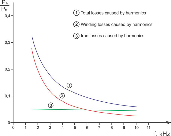
There are at least three issues with variable frequency drive service: 1: harmonics can create high voltage spikes that break down insulation, 2: harmonics cause extra heating in the windings, causing extra cooling demand, and 3: running the motor slower than full speed reduces the regular fan speed, on a TEFC or open motor, and thus its ability to cool itself.
There are at least three issues with variable frequency drive service: 1: harmonics can create high voltage spikes that break down insulation, 2: harmonics cause extra heating in the windings, causing extra cooling demand, and 3: running the motor slower than full speed reduces the regular fan speed, on a TEFC or open motor, and thus its ability to cool itself.
Well, even when the switch is open (i.e.) even when the fixed & moving contacts of the switching devices are apart, there is still an insulation between the fixed & moving contacts. Like any material in this earth, this insulating material also has an electrical resistance and this resistance is called Insulation Resistance. And, even when the switch is OFF, the incoming side would still be live with the system voltage. Wherever & whenever a voltage is there and a resistance is there, there is bound to be current flow, following Ohm's Law. True to this, there would definitely be a current flow between the open fixed & moving contacts of the switch, through this insulation resistance. This current is called the 'leakage current'.
Featured Articles
Variable Frequency Drive Harmonics and ...
A discussion of the benefits of variable frequency drives often leads to a question regarding electrical harmonic distortion ...
Three phase inverters
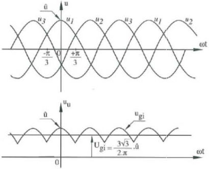
 In the variable frequency drive rectifier paper, it explains how to go from three phase alternating current voltage to a direct ...
 In the variable frequency drive rectifier paper, it explains how to go from three phase alternating current voltage to a direct ...
Variable frequency drive Advantages & ...
VFDs are good for variable speed, in a water pump this is used to maintain a steady pressure, they will smooth out variances in ...
Variable frequency drive Rectifier
 To understand variable frequency drive (VFD) better, it's necessary to explain some of the main parts of the variable frequency ...
 To understand variable frequency drive (VFD) better, it's necessary to explain some of the main parts of the variable frequency ...
VFD controlled Induction motor ...
 This paper presents a procedure to measure the efficiency on an induction motor fed by a VFD by the all operation range to speed ...
 This paper presents a procedure to measure the efficiency on an induction motor fed by a VFD by the all operation range to speed ...
VFD manufacturers
