Home » Applications » VFD Typical Applications
VFD Typical Applications
VFDs are widely used to control the speed of conveyor systems, blower speeds, pump speeds, machine tool speeds, & other applications that require variable speed with variable torque. In some applications such as speed control for a conveyor, the VFD is installed with a remote potentiometer that personnel can adjust manually to set the speed for the conveyor. In this type of application, the personnel who use the conveyor can manually set the motor speed with the minimum & maximum frequency that is programmed into the VFD parameters.
In other applications, such as blower-speed control or pump-speed control, the VFD can be controlled by a 4-20 mA or 0-10 volt input signal that comes from a microprocessor controller. When the input signal for the VFD is provided from a controller, the system is considered to be a closed loop. For example, in a system where the VFD is controlling the speed of a blower, a temperature sensor can be used to determine the temperature of a room. If it's too cold & the blower is moving warm air, the speed of the blower can be increased. If the temperature becomes too hot, the speed of the blower can be slowed until the temperature returns to the correct setpoint. If the VFD is used to control the level of product in a tank by varying the speed of a pump, a level sensor can be connected to a controller. If the level of the tank is becoming low, the VFD can increase the speed of the motor & pump, if the level is too high, the speed can be reduced.
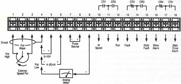
The diagrams below shows an example of the field wiring connections at the terminal boards of a VFD for a typical application. In this case the VFD diagram is for a Gozuk VFD. The top diagram shows the external control signals that are connected to terminal board 2 (TB2) of the VFD. You can see that the command signal can be an external potentiometer connected to terminals 1, 2, & 3, or it can be a 0-10 volt signal connected to terminals 4 & 5, or it can be a 4-20 mA signal connected to terminals 4-6. This terminal board also provides NO & NC contacts to indicate the VFD is at speed, running, faulted, or has a VFD alarm. These contacts are used as part of fault or safety circuits for the system.

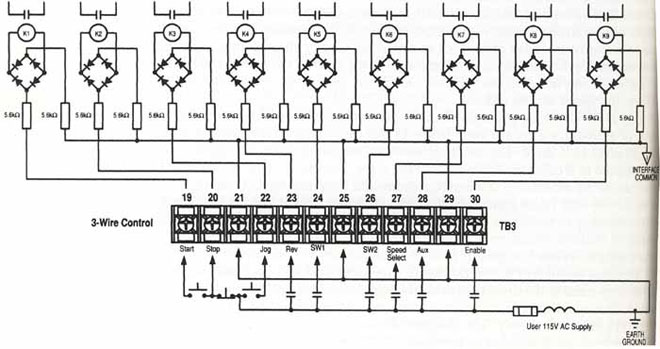
Terminal board 3 (TB3) in the second diagram shows the start & stop switches that must be connected to the VFD to provide the signals to cause it to start & become enabled. The signal voltage for this board can be selected as 5 volts TTL, 28 volts DC, or 115 volts AC supply. The diagram shown uses 115 volts AC. Start, stop, jog buttons are connected to terminals 19, 20, 22. A 115 volt signal must also be provided at terminal 30 to enable the VFD. Terminals 24 & 26 provide the inputs for switch SW1 & SW2, which will be used to make a two-bit binary. code to indicate the acceleration & deceleration parameters. Terminal 23 is used to set the motor in reverse from a remote switch. Terminals 21, 25, & 29 are the common for this board & since they are connected inside the board, the common from the transformer need only be connected to one of these terminals.

After the 115 volt AC signals that are used as inputs for this board are received they must be isolated & converted before they are sent to the microprocessor. The isolation & rectification portion of this board is shown in the first diagram. From the TB3 diagram (above) you can see that after each 115 volt AC signal is received, it's rectified & directed through a DC-powered relay to provide isolation before it's sent to the processor. The diagram also shows each signal connected to a set of resistors to drop the voltage & to a bridge rectifier to change the AC voltage to DC. The output of the bridge rectifier is connected to the coil of a DC relay. The contacts of the relay are connected to the processor inputs. Since this signal comes through a relay, there is total isolation between the 115 volt AC used in the field switches connected to this board & the contacts that are connected directly to the processor section of the VFD.
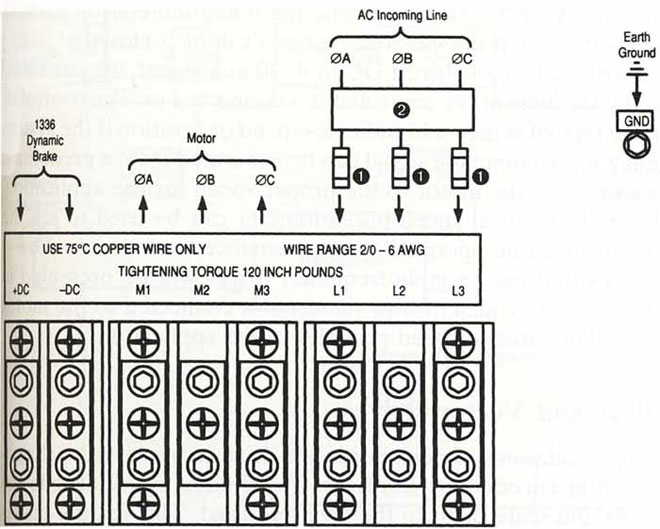
The high-voltage terminal board for the VFD is designated as TB1. This terminal board provides connections at the far right side for L1, L2, L3 where the three-phase 480 volt AC is connected. Terminals M1, M2, M3 are connections for the output of the VFD to the three-phase motor. Terminals -dc & +dc are located at the far left side of the terminal block & they provide DC voltage directly from the DC bus. This voltage is provided for a dynamic brake that can be added to the three phase motor. The dynamic brake provides a means to stop the motor shaft quickly.

In other applications, such as blower-speed control or pump-speed control, the VFD can be controlled by a 4-20 mA or 0-10 volt input signal that comes from a microprocessor controller. When the input signal for the VFD is provided from a controller, the system is considered to be a closed loop. For example, in a system where the VFD is controlling the speed of a blower, a temperature sensor can be used to determine the temperature of a room. If it's too cold & the blower is moving warm air, the speed of the blower can be increased. If the temperature becomes too hot, the speed of the blower can be slowed until the temperature returns to the correct setpoint. If the VFD is used to control the level of product in a tank by varying the speed of a pump, a level sensor can be connected to a controller. If the level of the tank is becoming low, the VFD can increase the speed of the motor & pump, if the level is too high, the speed can be reduced.
The diagrams below shows an example of the field wiring connections at the terminal boards of a VFD for a typical application. In this case the VFD diagram is for a Gozuk VFD. The top diagram shows the external control signals that are connected to terminal board 2 (TB2) of the VFD. You can see that the command signal can be an external potentiometer connected to terminals 1, 2, & 3, or it can be a 0-10 volt signal connected to terminals 4 & 5, or it can be a 4-20 mA signal connected to terminals 4-6. This terminal board also provides NO & NC contacts to indicate the VFD is at speed, running, faulted, or has a VFD alarm. These contacts are used as part of fault or safety circuits for the system.

Terminal board 3 (TB3) in the second diagram shows the start & stop switches that must be connected to the VFD to provide the signals to cause it to start & become enabled. The signal voltage for this board can be selected as 5 volts TTL, 28 volts DC, or 115 volts AC supply. The diagram shown uses 115 volts AC. Start, stop, jog buttons are connected to terminals 19, 20, 22. A 115 volt signal must also be provided at terminal 30 to enable the VFD. Terminals 24 & 26 provide the inputs for switch SW1 & SW2, which will be used to make a two-bit binary. code to indicate the acceleration & deceleration parameters. Terminal 23 is used to set the motor in reverse from a remote switch. Terminals 21, 25, & 29 are the common for this board & since they are connected inside the board, the common from the transformer need only be connected to one of these terminals.

After the 115 volt AC signals that are used as inputs for this board are received they must be isolated & converted before they are sent to the microprocessor. The isolation & rectification portion of this board is shown in the first diagram. From the TB3 diagram (above) you can see that after each 115 volt AC signal is received, it's rectified & directed through a DC-powered relay to provide isolation before it's sent to the processor. The diagram also shows each signal connected to a set of resistors to drop the voltage & to a bridge rectifier to change the AC voltage to DC. The output of the bridge rectifier is connected to the coil of a DC relay. The contacts of the relay are connected to the processor inputs. Since this signal comes through a relay, there is total isolation between the 115 volt AC used in the field switches connected to this board & the contacts that are connected directly to the processor section of the VFD.
The high-voltage terminal board for the VFD is designated as TB1. This terminal board provides connections at the far right side for L1, L2, L3 where the three-phase 480 volt AC is connected. Terminals M1, M2, M3 are connections for the output of the VFD to the three-phase motor. Terminals -dc & +dc are located at the far left side of the terminal block & they provide DC voltage directly from the DC bus. This voltage is provided for a dynamic brake that can be added to the three phase motor. The dynamic brake provides a means to stop the motor shaft quickly.

Post a Comment:
You may also like:
Featured Articles
Variable frequency drive application ...
 Variable Frequency Drive (VFD) can be used in lots of fields. Variable frequency drives are widely used to control the speed of ...
 Variable Frequency Drive (VFD) can be used in lots of fields. Variable frequency drives are widely used to control the speed of ...
VFD manufacturers
