VFD PWM Waveform
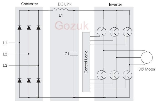
There are several PWM modulation techniques. It is beyond the scope of this discussion to describe them all in detail. The following text and illustrations describe a typical pulse width modulation method. A VFD IGBT (or other type switching device) can be switched on connecting the motor to the positive value of DC voltage (650 VDC from the converter). Current flows in the motor. The VFD IGBT is switched on for a short period of time, allowing only a small amount of current to build up in the motor and then switched off. The VFD IGBT is switched on and left on for progressively longer periods of time, allowing current to build up to higher levels until current in the motor reaches a peak. The VFD IGBT is then switched on for progressively shorter periods of time, decreasing current build up in the motor. The negative half of the sine wave is generated by switching an IGBT connected to the negative value of the converted DC voltage.

The diagram below shows a common waveform for a pulse-width modulation (PWM) circuit in the VFD. The transistors in the PWM circuit are switched on & off approximately 12 times each half-cycle. The on & off cycles create the overall frequency waveform for the output signal. The output waveform of the PWM section looks like a traditional three-phase signal to the motor. If one places an isolated-case oscilloscope across any two of the output leads of the VFD, one will see a signal that looks similar to the one in the diagram.
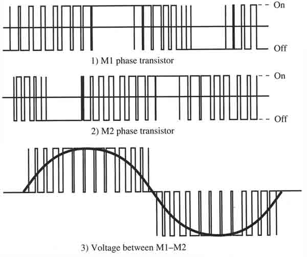
If one is using a digital voltmeter to measure the output voltage on a VFD, one must be aware that some digital voltmeters will not read the AC voltage from this section accurately because of the switching frequency of the transistors. The digital voltmeters tend to read the VFD's output voltage higher than it actually is because the voltmeter may be fast enough to sample some of the individual waveforms created when the transistors are switched on & off rapidly. An analog meter may show the voltage more accurately because the needle can't change as fast as the transistor is switched on & off. For this reason some VFD manufacturers provide an LED display to show an accurate voltage reading right on the face of the VFD.
Output waveform of the PWM section of the VFD. Notice all of the points where the transistor is switched on & off inside each half-wave.
PWM Voltage and Current
The more sinusoidal current output produced by the PWM reduces the torque pulsations, low speed motor cogging, and motor losses noticeable when using a six-step output.

The voltage and frequency is controlled electronically by circuitry within the VFD. The fixed DC voltage (650 VDC) is modulated or clipped with this method to provide a variable voltage and frequency. At low output frequencies a low output voltage is required. The switching devices are turned on for shorter periods of time. Voltage and current build up in the motor is low. At high output frequencies a high voltage is required. The switching devices are turned on for longer periods of time, allowing voltage and current to build up to higher levels in the motor.

The diagram below shows a common waveform for a pulse-width modulation (PWM) circuit in the VFD. The transistors in the PWM circuit are switched on & off approximately 12 times each half-cycle. The on & off cycles create the overall frequency waveform for the output signal. The output waveform of the PWM section looks like a traditional three-phase signal to the motor. If one places an isolated-case oscilloscope across any two of the output leads of the VFD, one will see a signal that looks similar to the one in the diagram.

If one is using a digital voltmeter to measure the output voltage on a VFD, one must be aware that some digital voltmeters will not read the AC voltage from this section accurately because of the switching frequency of the transistors. The digital voltmeters tend to read the VFD's output voltage higher than it actually is because the voltmeter may be fast enough to sample some of the individual waveforms created when the transistors are switched on & off rapidly. An analog meter may show the voltage more accurately because the needle can't change as fast as the transistor is switched on & off. For this reason some VFD manufacturers provide an LED display to show an accurate voltage reading right on the face of the VFD.
Output waveform of the PWM section of the VFD. Notice all of the points where the transistor is switched on & off inside each half-wave.
PWM Voltage and Current
The more sinusoidal current output produced by the PWM reduces the torque pulsations, low speed motor cogging, and motor losses noticeable when using a six-step output.

The voltage and frequency is controlled electronically by circuitry within the VFD. The fixed DC voltage (650 VDC) is modulated or clipped with this method to provide a variable voltage and frequency. At low output frequencies a low output voltage is required. The switching devices are turned on for shorter periods of time. Voltage and current build up in the motor is low. At high output frequencies a high voltage is required. The switching devices are turned on for longer periods of time, allowing voltage and current to build up to higher levels in the motor.
Post a Comment:
You may also like:
Featured Articles
Variable frequency drive Rectifier
 To understand variable frequency drive (VFD) better, it's necessary to explain some of the main parts of the variable frequency ...
 To understand variable frequency drive (VFD) better, it's necessary to explain some of the main parts of the variable frequency ...
VFD controlled Induction motor ...
 This paper presents a procedure to measure the efficiency on an induction motor fed by a VFD by the all operation range to speed ...
 This paper presents a procedure to measure the efficiency on an induction motor fed by a VFD by the all operation range to speed ...
What is VFD, How it works? - VFD ...
 VFD is shorted for Variable Frequency Drive (also known as AC Drives and Inverters) -- that's used to make an AC motor working in ...
 VFD is shorted for Variable Frequency Drive (also known as AC Drives and Inverters) -- that's used to make an AC motor working in ...
VFD: Pulse Width Modulation (PWM)
 Pulse Width Modulation (PWM) VFDs provide a more sinusoidal current output to control frequency and voltage supplied to an AC ...
 Pulse Width Modulation (PWM) VFDs provide a more sinusoidal current output to control frequency and voltage supplied to an AC ...
Variable frequency drive Advantages & ...
VFDs are good for variable speed, in a water pump this is used to maintain a steady pressure, they will smooth out variances in ...

VFD manufacturers

The but is that manufacture who quote 'pure sine wave' don't define the load and the voltage out is definitely not a sine wave.
Please consider loads such as resistive or rectified capacitive inputs. Here the current wave forms are not in any way similar to a sine wave.