VFD Power Source
One can get a better idea of how the diodes in the rectifier and the devices in the filter and regulator sections of a circuit all work together when one sees a complete electronic circuit for an operational system. Following Figure shows the electrical diagram of a VFD that is commonly used in industrial applications. From this diagram notice that the VFD circuit uses three phase power source voltage, so a three phase full-wave bridge rectifier is used. Keep in mind that it's encapsulated so one doesn't see each of the diodes. Rather one would find the terminals for the three input terminals and the two dc output terminals.
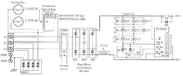
This circuit also uses metal oxide varistors (MOVs) to check for an over-voltage condition at the incoming power source. Notice that the electronic symbol that looks like two diodes connected end to end is used instead of the box symbol that was used for MOVs in the previous figures. The MOVs are connected between each of the three phases of incoming power and ground to protect the electronic parts from excessive supply voltage. The fuses in the system only check for over-current, and they are not aware of an over-voltage condition. If an over-voltage condition occurs, the MOVs will go into conduction (lower their resistance) and cause an over-current condition that will make the fuse open. The fuses that protect the supply voltage are not shown in this diagram. They would be located in series with the L1, L2, and L3 terminals of the supply voltage.
The next components in the dc voltage section of the VFD are the choke (inductor) and capacitors (filter). The inductor in this circuit is labeled L1 for inductor 1 and it's connected in series with the dc negative voltage line and the capacitors that are connected in parallel across the dc lines. The positive dc and negative dc line will be called the dc bibs because they supply all dc power to the inverter section of the VFD. More than one capacitor is used on larger VFDs to provide the correct amount of filtering, which will make the pulsing half-wave dc nearly pure dc.
The capacitors will have resistors connected across their terminals. The function of these resistors is to provide a means to bleed the capacitors down when power is de-energized. Always treat the capacitors in a power source as though they are fully charged. This will avoid any unfortunate accidents from the high voltage they store even when the main power is turned off. It's more important to understand that these capacitors will constantly charge and discharge with every half-wave when power is applied, so they can continually discharge high voltage to you if you come into contact with them. The capacitor pre-charge circuit is connected to the bank of capacitors used in the filter and ensures that when voltage is initially applied to the capacitors, it's ramped up slowly so that the capacitors don't absorb maximum voltage. This circuit will help prevent the capacitors from charging too quickly and becoming damaged.
Post a Comment:
You may also like:
Featured Articles
Variable frequency drive Rectifier
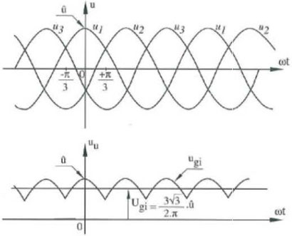 To understand variable frequency drive (VFD) better, it's necessary to explain some of the main parts of the variable frequency ...
 To understand variable frequency drive (VFD) better, it's necessary to explain some of the main parts of the variable frequency ...
What is VFD, How it works? - VFD ...
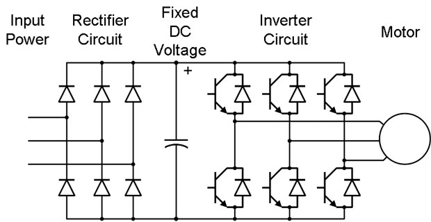 VFD is shorted for Variable Frequency Drive (also known as AC Drives and Inverters) -- that's used to make an AC motor working in ...
 VFD is shorted for Variable Frequency Drive (also known as AC Drives and Inverters) -- that's used to make an AC motor working in ...
VFD controlled Induction motor ...
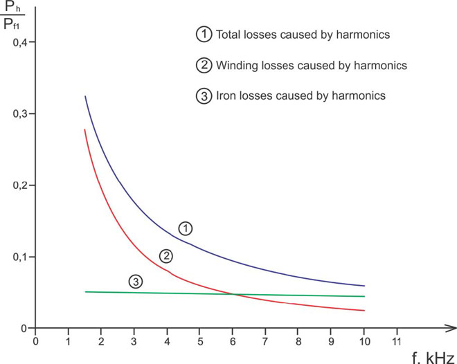 This paper presents a procedure to measure the efficiency on an induction motor fed by a VFD by the all operation range to speed ...
 This paper presents a procedure to measure the efficiency on an induction motor fed by a VFD by the all operation range to speed ...
VFD: Insulated Gate Bipolar Transistor ...
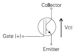 IGBT (insulated gate bipolar transistor) provides a high switching speed necessary for PWM VFD operation. IGBTs are capable of ...
 IGBT (insulated gate bipolar transistor) provides a high switching speed necessary for PWM VFD operation. IGBTs are capable of ...
Three phase inverters
 In the variable frequency drive rectifier paper, it explains how to go from three phase alternating current voltage to a direct ...
 In the variable frequency drive rectifier paper, it explains how to go from three phase alternating current voltage to a direct ...
VFD manufacturers
