VFD Harmonics Effect
History has shown that electrical VFDs using power electronics have not been that network-friendly. Either the VFD has operated at a poor power factor that decreases with a decrease of motor speed or it has injected large harmonic currents back into the supply network. All power electronic systems inject harmonic currents into the network due to their non-linearity. The effects of the harmonics that are injected into the network include overheating of transformers, cables, motors, alternators and capacitors; and maloperation of protection relays and other instrumentation that were not designed with an insensitivity to harmonics in the supply. Thus, some form of harmonic mitigation is required. This can be implemented through structural modification within the VFD system or through external filtering.
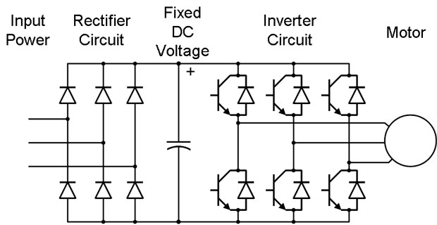
The most common input rectifier used within three-phase VSI VFDs is the six-pulse diode bridge. To reduce the harmonic currents injected into the network, the pulse number of the rectifier could be increased to 12, 18, 24, 36 or higher. The unfortunate part of this solution is the addition of a higher cost and a special multi secondary transformer with two, three, four, six or more secondary windings with the appropriate phase shift between these secondary windings.
The total harmonic current distortion for a six-pulse system with line chokes is in the order of 30%, while for a 12-pulse configuration the figure is approximately 12%, and for an 18-pulse configuration the figure is approximately 6%. This technique has been applied to dc drives, Current Source Inverter (CSI) VFDs and direct conversion VFDs where the diodes have been replaced with thyristors.
The current waveform in this design is similar to the diode design but the total power factor with a partial load is poor. This causes the apparent current to be higher, with the resulting higher absolute harmonic currents.
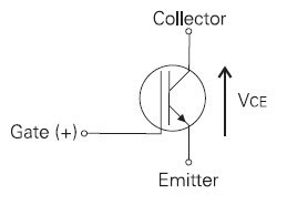
If the diodes are replaced with self commutated components such as IGBTs, in a configuration similar to the output inverter then several benefits can be realized.
These include the ability to permit bi-directional power flow, control the dc bus voltage level and the displacement power factor independently, regardless of the power flow direction, safe function during supply interruptions, possibility to generate reactive power and the reduction of total harmonic levels of low order harmonics to less than 5%. The higher order harmonics can be absorbed by a LCL filter. If the input active rectifier comprises the same hardware as the output inverter, then the spares inventory is reduced to a minimum.
The harmonic currents can also be reduced by increasing the size of the inductor in the ac input or dc bus. If the VFD is not fitted with any inductance then, depending on the supply impedance, the total harmonic current distortion could be of the order of 130% for a 415 V 50 Hz system.
With the same supply impedance and an inductance of 100 mH per motor kW, the total harmonic current would be of the order of 30%. Increasing the inductance by too much will have implications from a motor control perspective as well as cost and the volume of the VFD.
Total harmonic distortion can also be reduced by the addition of external filtering equipment. This equipment can either be of the passive type such as one or more LC filters tuned to frequencies just below the dominant harmonics. The other type of filter that can be employed is the active filter.
These units compensate for the harmonics generated by nonlinear loads by generating the same harmonic currents having the same amplitude but in opposite phase. Thus the resultant harmonic currents are at near zero levels. This solution is relatively more expensive than the other methods described.
Post a Comment:
You may also like:
Featured Articles
What is VFD, How it works? - VFD ...
 VFD is shorted for Variable Frequency Drive (also known as AC Drives and Inverters) -- that's used to make an AC motor working in ...
 VFD is shorted for Variable Frequency Drive (also known as AC Drives and Inverters) -- that's used to make an AC motor working in ...
VFD: Insulated Gate Bipolar Transistor ...
 IGBT (insulated gate bipolar transistor) provides a high switching speed necessary for PWM VFD operation. IGBTs are capable of ...
 IGBT (insulated gate bipolar transistor) provides a high switching speed necessary for PWM VFD operation. IGBTs are capable of ...
Three phase inverters
 In the variable frequency drive rectifier paper, it explains how to go from three phase alternating current voltage to a direct ...
 In the variable frequency drive rectifier paper, it explains how to go from three phase alternating current voltage to a direct ...
Variable Frequency Drive Harmonics and ...
A discussion of the benefits of variable frequency drives often leads to a question regarding electrical harmonic distortion ...
Variable frequency drive Energy saving
 Energy can be saved in a VFD by reducing the losses in the electric motor or by reducing the energy consumption of the variable ...
 Energy can be saved in a VFD by reducing the losses in the electric motor or by reducing the energy consumption of the variable ...
VFD manufacturers
