Home » Applications » VFD for Variable Air Volume system
VFD for Variable Air Volume system
A Variable Air Volume system has three control loops:
As shown in Figure1, the Variable Air Volume Air Handling Unit Optimization Algorithm interacts with all three control loops. The real-time inputs to the Variable Air Volume Air Handling Unit Optimization Algorithm are the duct static pressure, the command to the VFD. (0% - 100%) and the command to each of the Variable Air Volume box dampers (0% 100%). The outputs of the Variable Air Volume Air Handling Unit Optimization Algorithm are the setpoint of the off-coil temperature control loop, the setpoint of the pressure control loop and the bias for the Variable Air Volume box temperature control loop.
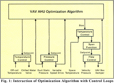
For simplicity, figure 1 does not show the other control parameters such as space temperature setpoint and loop tuning parameters that are not involved in the Variable Air Volume Air Handling Unit optimization algorithm.
Finite State Machine Representation
As shown in Figure 2, the Variable Air Volume Air Handling Unit Optimization Algorithm considers the Air Handling Unit to be in one of three states:
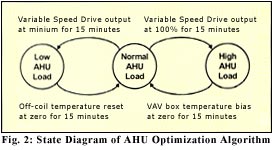
The Variable Air Volume Air Handling Unit Optimization Algorithm uses different optimization strategies for each state. Table 1 provides a synopsis of the optimization strategy used in each of the three states.
Normal Air Handling Unit Load State
An Air Handling Unit is designed to accommodate a range of heat loads. When the actual heat load is within this range, the Air Handling Unit will be in the Normal Air Handling Unit Load State.
As indicated in Table 1, the role of the Variable Air Volume Air Handling Unit Optimization Routine in the Normal Air Handling Unit Load State is to reset the static pressure setpoint based on Variable Air Volume box position. To appreciate the benefit of this optimization, it is useful to consider the implications of the conventional method of static pressure control using a fixed static pressure setpoint. There are two problems with conventional approach of fixed static pressure setpoint:
Selecting the Fixed Static Pressure Setpoint
If the static pressure setpoint is too low, some of the Variable Air Volume boxes will not be able to get enough air to provide comfort. Some Variable Air Volume boxes will haves their dampers 100% open but the actual flow will still be less than the desired flow. These boxes are "starved" for air and fail to achieve the space temperature setpoint. This situation is illustrated in Figure 3 below.
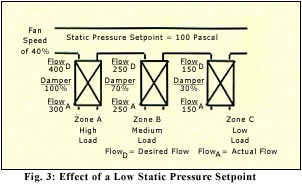
The low static pressure setpoint will cause the fan to run at a low speed and use little energy. However, the Variable Air Volume box in Zone A is starved. The actual flow is less than the desired flow, even though damper is 100% open. Zone A will get hotter as insufficient cool air is being provided. The building operator typically does not understand how the static pressure setpoint affects the variable frequency drive system. Operators often raise the static pressure setpoint after receiving complaints about hot spots and come to the conclusion that "higher is better". As a result, the static pressure setpoint is often set at an excessively high level, effectively converting the Variable Air Volume system into a constant volume system. The operator does not receive any complaints about he spots but does not realize that energy is being wasted.
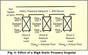
If the static pressure setpoint is too high, energy is wasted as the fan is working harder than truly necessary. In addition high static pressure setpoints lead to noise and controllability problems. This situation is illustrated in Figure 4. In this situation, there will be no comfort problems in the space. This is because, for each of the Variable Air Volume boxes, the actual flow is the same as the desired flow. In other words, none of the Variable Air Volume boxes are starved. The fan speed is much higher as compared to the previous condition as the fan must work harder to maintain the higher static pressure setpoint.
Having the least load, Zone C has the lowest airflow requirement of only 150 CFM. To achieve this airflow with the low static pressure setpoint, the damper was 30% open. To achieve the same airflow with the high static pressure setpoint, the damper was 10% open. We can see that increasing the static pressure setpoint will cause he Variable Air Volume box dampers to close to maintain the same desired airflow. Pushing the same volume of air through a smaller opening will increase the noise of the variable frequency drive system. In other words, a high static pressure setpoint increases the noise in the variable frequency drive system.
A high static pressure setpoint also reduces the controllability of the variable frequency drive system. This is illustrated in Figure 6. The airflow through a Variable Air Volume box will increase quickly as the damper starts to open. This can be seen in the non-linear characteristic of airflow versus damper position in Figure 5. Each Variable Air Volume box has a minimum flow and maximum flow programmed into the controller. The controller will position the damper to achieve a desired flow that will be between the minimum flow and the maximum flow. The minimum flow and the maximum flow are shown as the horizontal lines in Figure 5.
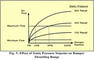
We can see from Figure 5 that with a static pressure setpoint of 100 Pascal, the Variable Air Volume box cannot achieve the maximum airflow condition, even with the damper 100% open. This means that the Variable Air Volume box will often be starved and space comfort will often not be achieved with a static pressure setpoint of 100 Pascal. The Variable Air Volume box will be able to achieve the maximum airflow condition with a static pressure setpoint of either 200 Pascal or 500 Pascal. The impact of increasing the static pressure setpoint is to decrease the throttling range of the damper. Throttling range is defined as the difference between the signal required to achieve minimum position and the signal to achieve maximum position. In Figure 5, the throttling range of the damper when the static pressure setpoint is 200 Pascal is roughly 48% and the throttling range of the damper when the static pressure setpoint is 500 Pascal is roughly 14%. See Table 2.
Table 2 : Effect of Static Pressure Setpoint on Damper Throttling Range
Increasing the static pressure setpoint from 200 Pascal to 500 Pascal cuts the damper throttling range by two thirds. As the throttling range decreases, the variable frequency drive system is more sensitive to control adjustments. For example, if he minimum airflow is 300 CFM and the maximum airflow is 1000 CFM, a 1% change in damper position will change the airflow by less than 15 CFM when the static pressure setpoint is 200 Pascal. Changing the static pressure setpoint to 500 Pascal would result in a change of 50 CFM for 1% change in damper position. It is much more difficult to control the airflow accurately with a high staitc pressure. In addition, Variable Air Volume box damper actuators use stepper motors with a finite positioning resolution. This positioning resolution increases the difficulty in achieving stable box control with high static pressures.
Locating the Static Pressure Sensor
During the design phase, a certain static pressure is assumed in the duct work, Static pressure sensors are located in the ductwork at the points of minimum static pressure and the setpoint is initialized at the static pressure assumed during the design phase. This approach will hopefully ensure that the static pressure at all points in the ductwork is at least the value assumed during the design phase. In reality, Variable Air Volume boxes only come in fixed sizes and it is impossible to accurately determine the point of lowest static pressure in the ductwork, especially when there is a complicated ductwork design. As a result, the design static pressure may not be the optimal setpoint for the actual installed variable frequency drive system.
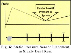
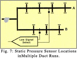
As shown in Figure 6, in the simplified case of one straight run of ductwork, this is one half to two thirds of the way along the duct run. When the ductwork has two or more branches, a static pressure sensor is placed at the point of lowest static pressure in each of the duct runs and the fan is controlled to ensure that the lowest static pressure in the entire ductwork system is the static pressure setpoint.
Consider the example in Figure 7 of branch A serving the east sides of the building and branch B serving west side of the building. In the morning, the static pressure on the east side would be low and the fun would be controlled by sensor A and in the afternoon, the fan would be controlled by sensor B,
With a fixed static pressure setpoint, it is important to sense the static pressure at the minimum point in the ductwork to ensure that the static pressure at that point is at the setpoint value. If it is achieved then the static pressure in all other portions of the ductwork will be higher than the setpoint ensuring that there are no starved boxes.
However, since the point of lowest static pressure in the ductwork varies over time and with a shifting building load, multiple sensors are required. Because of the complexity of real-life duct designs, even with multiple sensors, it is not possible to guarantee that the lowest pressure point in the variable frequency drive system is being sensed. In addition, each static pressure sensor increases booth the first cost and the maintenance cost for the variable frequency drive system.
Dynamically Resetting the Static Pressure Setpoint
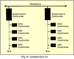
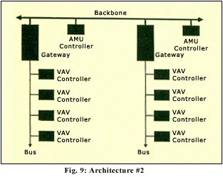
In his book, "Direct Digital Controls for HVAC Systems", Hartman (1983) describes a "Terminal Regulated Air Volume" (TRAV) algorithm in which he supply fan speed is regulated to meet zone airflow requirements instead of a static pressure setpoint. Terminal Regulated Air Volume will save energy but it requires that the fan be controlled based on a fan be controlled based on a summation of the desired airflow from each Variable Air Volume box. This requires that a Terminal Regulated Air Volume algorithm, resident in the Air Handling Unit fan controller, collect information from each of the Variable Air Volume boxes to calculate the appropriate control signal. Completing the control loop across the network rather than within a single controller can overload the capability of the communications network. In the cases where the communications between the Air Handling Unit controller and the respective Variable Air Volume controllers are isolated by a supervisory controller (figure 8), this is less of an issue. In cases where every message between any Variable Air Volume controller and any Air Handling Unit controller has to be carried by a single common backbone (Figure 9), the variable frequency drive system can become overloaded trying to do realtime control.
In their article in the April 1993 ASHRAE Journal, "Integrating Variable Air Volume Zone Requirements with Supply Fan Operation", Warren and Norford, describe a static pressure reset algorithm based on the number of Variable Air Volume zones experiencing a starved box condition. The algorithm increases the static pressure setpoint by 5% whenever only one Variable Air Volume zone is experiencing a starved box condition. This algorithm and the algorithm proposed in this paper are superior to Terminal Regulated Air Volume in that the real-time control algorithm of the VFD is contained in a single controller while the setpoint is updated at a much less frequent interval, thus dramatically reducing the traffic on the network.
The static pressure resetting algorithm in this paper takes a similar approach to Warren and Norford. The principal difference is that the proposed algorithm in this paper uses actual damper position rather than the starved box condition to reset the pressure. The advantage of the proposed algorithm is that approximately the same level of savings will be achieved without any starved box conditions that indicate comfort is being compromised. The article estimated savings in a case study of 19% to 42% when compared to a fixed static pressure setpoint and the proposed algorithm in this paper should deliver similar results.
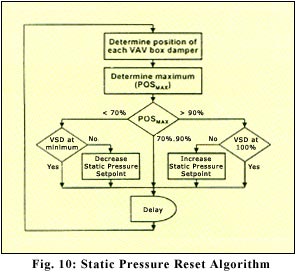
The Variable Air Volume Air Handling Unit Optimization Algorithm constantly resets the static pressure setpoint to the lowest possible value that avoids a starved box condition,. The algorithm shown in Figure 11 will ensure that the static pressure setpoint is set to a value such that the Variable Air Volume box that is open the most is between 70% and 90%. This algorithm has the following parameters:
Low Air Handling Unit Load State
The Variable Air Volume Air Handling Unit Optimization Algorithm transitions from the Normal Air Handling Unit Load State to the Low Air Handling Unit Load State when the VFD output has been at the minimum position for 15 minutes (adjustable). It can be seen from Figure 10 that while the VFD output is at minimum, the static pressure setpoint remains fixed. The Variable Air Volume Air Handling Unit Optimization Algorithm will store this static pressure setpoint (SPMIN) for use in the Low Air Handling Unit Load State optimization routine.
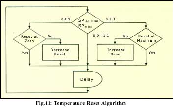
In the Low Air Handling Unit Load State, the fan speed is fixed at the minimum (i.e.40%) and does not respond to changes in static pressure. As shown in Figure 12, every five minutes (adjustable), the temperature reset algorithm calculates the ratio of he actual static pressure (SPACTUAL) to the static pressure setpoint (SPMIN). If the actual static pressure is more than ten percent greater than the setpoint (adjustable), this indicates that the Load in the space has decreased and it is appropriate to increase the off-coil temperature setpoint. Increasing the off-coil temperature will cause the zones to call for more airflow and will lower the actual static pressure. Increasing the off-coil temperature will increase the space humidity, limiting the amount of reset. Similarly, as the load in the space increases, the static pressure in the ductwork will drop. When the static pressure in the ductwork drops to less than ninety percent of the setpoint (adjustable), the off-coil temperature setpoint is reduced. It is reasonable to adjust the amount of reset by 0.1°C on each repetition of the algorithm.
When the reset has remained at zero for fifteen minutes (adjustable) this indicates that the load has increased to the point that the state of the Variable Air Volume Air Handling Unit Optimization Algorithm should change from Low Air Handling Unit Load State to Normal Air Handling Unit Load State. When the Variable Air Volume Air Handling Unit Optimization Algorithm returns to the Normal Load State, the off-coil temperature a will no longer be reset and the fan speed a will be modulated based on the static pressure.
High Air Handling Unit Load State
The Variable Air Volume Air Handling Unit Optimization Algorithm transitions from the Normal Air Handling Unit Load State to the High Air Handling Unit Load State when the VFD output has been at 100% for 15 minutes (adjustable). It can be seen from Figure 10 that while the VFD output is at 100%, the static pressure setpoint remains fixed. The Variable Air Volume Air Handling Unit Optimization Algorithm will store this static pressure setpoint (SPMAX) for use in the High Air Handling Unit Load State Optimization routine.
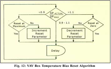
In the High Air Handling Unit State, the fan speed is at 100% and does not respond to changes in static pressure. As shown in Figure 12, every five minutes (adjustable), the Reset Algorithm calculates the ratio of the actual static pressure (SPACTUAL) to the static pressure setpoint (SPMAX). As the load increases, SPACTUAL will drop below SPMAX and the amount of reset will be incremented. This reset value is used to adjust the temperature bias for each Variable Air Volume box as shown in Table 3. When the Reset Parameter has remained at zero for fifteen minutes (adjustable) this indicates that the load has decreased to the point that the states of the Variable Air Volume Air Handling Unit.
Optimization Algorithm should change from High Air Handling Unit Load State to Normal Air Handling Unit Load State. When the Variable Air Volume Air Handling Unit Optimization Algorithm returns to the Normal Load State, the temperature bias for the Variable Air Volume boxes will no longer be reset and the fan speed a will be modulated based on the static pressure.
Real-Time Diagnostic
Figure 10 shows that during the Normal Air Handling Unit Load State, the Variable Air Volume box damper that is open the most is identified and used to determine if the static pressure setpoint should be changed. The Variable Air Volume box damper that is open the most is the zone calling for the most cooling at that time.
The Variable Air Volume Air Handling Unit Optimization Algorithm should keep track of which Variable Air Volume box has been selected as having POSMAX. In most cases, the same Variable Air Volume box will consistently have POSMAX and will have the greatest impact on the amount of energy savings possible through static pressure reset. If the Variable Air Volume Air Handling Unit Optimization Algorithm determines that a specific Variable Air Volume box has POSMAX more than 50% of the time, the operator should be alerted. This represents an opportunity to increase the energy savings in the variable frequency drive system using the following strategies:
The appropriate control of a Variable Air Volume Air Handling Unit can deliver significant energy savings while optimizing comfort levels.
- Temperature Control Loop - The chilled water valve is modulated to achieve the desired off-coil temperature.
- Pressure Control Loop - The VFD is modulated to achieve the desired duct static pressure
- Variable Air Volume Box Control Loop - The Variable Air Volume box damper is modulated to deliver the desired airflow as established by the temperature control loop.
As shown in Figure1, the Variable Air Volume Air Handling Unit Optimization Algorithm interacts with all three control loops. The real-time inputs to the Variable Air Volume Air Handling Unit Optimization Algorithm are the duct static pressure, the command to the VFD. (0% - 100%) and the command to each of the Variable Air Volume box dampers (0% 100%). The outputs of the Variable Air Volume Air Handling Unit Optimization Algorithm are the setpoint of the off-coil temperature control loop, the setpoint of the pressure control loop and the bias for the Variable Air Volume box temperature control loop.

For simplicity, figure 1 does not show the other control parameters such as space temperature setpoint and loop tuning parameters that are not involved in the Variable Air Volume Air Handling Unit optimization algorithm.
Finite State Machine Representation
As shown in Figure 2, the Variable Air Volume Air Handling Unit Optimization Algorithm considers the Air Handling Unit to be in one of three states:
- Low Air Handling Unit Load -During periods of minimal heat load (i.e. low occupancy at night)
- Normal Air Handling Unit Load - During typical periods (this is the initial state of the optimization algorithm)
- High Air Handling Unit Load - During periods of very high heat load (i.e. high occupancy in the afternoon)

The Variable Air Volume Air Handling Unit Optimization Algorithm uses different optimization strategies for each state. Table 1 provides a synopsis of the optimization strategy used in each of the three states.
Normal Air Handling Unit Load State
An Air Handling Unit is designed to accommodate a range of heat loads. When the actual heat load is within this range, the Air Handling Unit will be in the Normal Air Handling Unit Load State.
As indicated in Table 1, the role of the Variable Air Volume Air Handling Unit Optimization Routine in the Normal Air Handling Unit Load State is to reset the static pressure setpoint based on Variable Air Volume box position. To appreciate the benefit of this optimization, it is useful to consider the implications of the conventional method of static pressure control using a fixed static pressure setpoint. There are two problems with conventional approach of fixed static pressure setpoint:
- Selecting the fixed static pressure setpoint
- Locating he static pressure sensor
| Low Air Handling Unit Load state High | Normal Air Handling Unit Load State | Air Handling Unit Load State |
|
Fix VFD output at minimum |
Fix off-coil temperature setpoint |
Fix VFD output at maximum |
| Do not reset temperature bias of Variable Air Volume boxes | Do not reset temperature bias of Variable Air Volume boxes | Fix off-coil temperature setpoint |
|
Reset off-coil temperature setpoint to maintain static pressure setpoint |
Reset static pressure setpoint based on Variable Air Volume box damper position | Reset temperature bias of all Variable Air Volume boxes to maintain static pressure setpoint |
Selecting the Fixed Static Pressure Setpoint
If the static pressure setpoint is too low, some of the Variable Air Volume boxes will not be able to get enough air to provide comfort. Some Variable Air Volume boxes will haves their dampers 100% open but the actual flow will still be less than the desired flow. These boxes are "starved" for air and fail to achieve the space temperature setpoint. This situation is illustrated in Figure 3 below.


The low static pressure setpoint will cause the fan to run at a low speed and use little energy. However, the Variable Air Volume box in Zone A is starved. The actual flow is less than the desired flow, even though damper is 100% open. Zone A will get hotter as insufficient cool air is being provided. The building operator typically does not understand how the static pressure setpoint affects the variable frequency drive system. Operators often raise the static pressure setpoint after receiving complaints about hot spots and come to the conclusion that "higher is better". As a result, the static pressure setpoint is often set at an excessively high level, effectively converting the Variable Air Volume system into a constant volume system. The operator does not receive any complaints about he spots but does not realize that energy is being wasted.
If the static pressure setpoint is too high, energy is wasted as the fan is working harder than truly necessary. In addition high static pressure setpoints lead to noise and controllability problems. This situation is illustrated in Figure 4. In this situation, there will be no comfort problems in the space. This is because, for each of the Variable Air Volume boxes, the actual flow is the same as the desired flow. In other words, none of the Variable Air Volume boxes are starved. The fan speed is much higher as compared to the previous condition as the fan must work harder to maintain the higher static pressure setpoint.
Having the least load, Zone C has the lowest airflow requirement of only 150 CFM. To achieve this airflow with the low static pressure setpoint, the damper was 30% open. To achieve the same airflow with the high static pressure setpoint, the damper was 10% open. We can see that increasing the static pressure setpoint will cause he Variable Air Volume box dampers to close to maintain the same desired airflow. Pushing the same volume of air through a smaller opening will increase the noise of the variable frequency drive system. In other words, a high static pressure setpoint increases the noise in the variable frequency drive system.
A high static pressure setpoint also reduces the controllability of the variable frequency drive system. This is illustrated in Figure 6. The airflow through a Variable Air Volume box will increase quickly as the damper starts to open. This can be seen in the non-linear characteristic of airflow versus damper position in Figure 5. Each Variable Air Volume box has a minimum flow and maximum flow programmed into the controller. The controller will position the damper to achieve a desired flow that will be between the minimum flow and the maximum flow. The minimum flow and the maximum flow are shown as the horizontal lines in Figure 5.

We can see from Figure 5 that with a static pressure setpoint of 100 Pascal, the Variable Air Volume box cannot achieve the maximum airflow condition, even with the damper 100% open. This means that the Variable Air Volume box will often be starved and space comfort will often not be achieved with a static pressure setpoint of 100 Pascal. The Variable Air Volume box will be able to achieve the maximum airflow condition with a static pressure setpoint of either 200 Pascal or 500 Pascal. The impact of increasing the static pressure setpoint is to decrease the throttling range of the damper. Throttling range is defined as the difference between the signal required to achieve minimum position and the signal to achieve maximum position. In Figure 5, the throttling range of the damper when the static pressure setpoint is 200 Pascal is roughly 48% and the throttling range of the damper when the static pressure setpoint is 500 Pascal is roughly 14%. See Table 2.
Table 2 : Effect of Static Pressure Setpoint on Damper Throttling Range
| Static Pressure Setpoint | Damper Position to Minimum Airflow | Damper Position Maximum Airflow | Throttling Range |
| 100 Pascal | 5% | Not possible | N.A. |
| 200 Pascal | 2% | 50% | 48% |
| 500 Pascal | 1% | 15% | 14% |
Increasing the static pressure setpoint from 200 Pascal to 500 Pascal cuts the damper throttling range by two thirds. As the throttling range decreases, the variable frequency drive system is more sensitive to control adjustments. For example, if he minimum airflow is 300 CFM and the maximum airflow is 1000 CFM, a 1% change in damper position will change the airflow by less than 15 CFM when the static pressure setpoint is 200 Pascal. Changing the static pressure setpoint to 500 Pascal would result in a change of 50 CFM for 1% change in damper position. It is much more difficult to control the airflow accurately with a high staitc pressure. In addition, Variable Air Volume box damper actuators use stepper motors with a finite positioning resolution. This positioning resolution increases the difficulty in achieving stable box control with high static pressures.


Locating the Static Pressure Sensor
During the design phase, a certain static pressure is assumed in the duct work, Static pressure sensors are located in the ductwork at the points of minimum static pressure and the setpoint is initialized at the static pressure assumed during the design phase. This approach will hopefully ensure that the static pressure at all points in the ductwork is at least the value assumed during the design phase. In reality, Variable Air Volume boxes only come in fixed sizes and it is impossible to accurately determine the point of lowest static pressure in the ductwork, especially when there is a complicated ductwork design. As a result, the design static pressure may not be the optimal setpoint for the actual installed variable frequency drive system.
As shown in Figure 6, in the simplified case of one straight run of ductwork, this is one half to two thirds of the way along the duct run. When the ductwork has two or more branches, a static pressure sensor is placed at the point of lowest static pressure in each of the duct runs and the fan is controlled to ensure that the lowest static pressure in the entire ductwork system is the static pressure setpoint.
Consider the example in Figure 7 of branch A serving the east sides of the building and branch B serving west side of the building. In the morning, the static pressure on the east side would be low and the fun would be controlled by sensor A and in the afternoon, the fan would be controlled by sensor B,
With a fixed static pressure setpoint, it is important to sense the static pressure at the minimum point in the ductwork to ensure that the static pressure at that point is at the setpoint value. If it is achieved then the static pressure in all other portions of the ductwork will be higher than the setpoint ensuring that there are no starved boxes.
However, since the point of lowest static pressure in the ductwork varies over time and with a shifting building load, multiple sensors are required. Because of the complexity of real-life duct designs, even with multiple sensors, it is not possible to guarantee that the lowest pressure point in the variable frequency drive system is being sensed. In addition, each static pressure sensor increases booth the first cost and the maintenance cost for the variable frequency drive system.
Dynamically Resetting the Static Pressure Setpoint
In his book, "Direct Digital Controls for HVAC Systems", Hartman (1983) describes a "Terminal Regulated Air Volume" (TRAV) algorithm in which he supply fan speed is regulated to meet zone airflow requirements instead of a static pressure setpoint. Terminal Regulated Air Volume will save energy but it requires that the fan be controlled based on a fan be controlled based on a summation of the desired airflow from each Variable Air Volume box. This requires that a Terminal Regulated Air Volume algorithm, resident in the Air Handling Unit fan controller, collect information from each of the Variable Air Volume boxes to calculate the appropriate control signal. Completing the control loop across the network rather than within a single controller can overload the capability of the communications network. In the cases where the communications between the Air Handling Unit controller and the respective Variable Air Volume controllers are isolated by a supervisory controller (figure 8), this is less of an issue. In cases where every message between any Variable Air Volume controller and any Air Handling Unit controller has to be carried by a single common backbone (Figure 9), the variable frequency drive system can become overloaded trying to do realtime control.


In their article in the April 1993 ASHRAE Journal, "Integrating Variable Air Volume Zone Requirements with Supply Fan Operation", Warren and Norford, describe a static pressure reset algorithm based on the number of Variable Air Volume zones experiencing a starved box condition. The algorithm increases the static pressure setpoint by 5% whenever only one Variable Air Volume zone is experiencing a starved box condition. This algorithm and the algorithm proposed in this paper are superior to Terminal Regulated Air Volume in that the real-time control algorithm of the VFD is contained in a single controller while the setpoint is updated at a much less frequent interval, thus dramatically reducing the traffic on the network.
The static pressure resetting algorithm in this paper takes a similar approach to Warren and Norford. The principal difference is that the proposed algorithm in this paper uses actual damper position rather than the starved box condition to reset the pressure. The advantage of the proposed algorithm is that approximately the same level of savings will be achieved without any starved box conditions that indicate comfort is being compromised. The article estimated savings in a case study of 19% to 42% when compared to a fixed static pressure setpoint and the proposed algorithm in this paper should deliver similar results.

The Variable Air Volume Air Handling Unit Optimization Algorithm constantly resets the static pressure setpoint to the lowest possible value that avoids a starved box condition,. The algorithm shown in Figure 11 will ensure that the static pressure setpoint is set to a value such that the Variable Air Volume box that is open the most is between 70% and 90%. This algorithm has the following parameters:
- 70-90% - Limits for POSMAX. The upper limit (90%) should be less than 100% to allow for an increasing limit (70%) should be sufficiently less than the upper limit to avoid frequent setpoint adjustments.
- Variable frequency drive Minimum - The lowest speed for which the fan remains stable (i.e. 40%).
- SetPoint Increment/Decrement - The amount that the setpoint is increased or decreased. A smaller value makes the algorithm slower to respond, but allows for finer control.
- Delay - The time required for the variable frequency drive system to stabilize after a setpoint adjustment. A smaller value makes the variable frequency drive system respond faster, but results in more processing and message passing. A value of less than three minutes may make the algorithm unstable as the variable frequency drive system may not have sufficient time to stabilize after a setpoint adjustment. A delay of five minutes has been used successfully.
Low Air Handling Unit Load State
The Variable Air Volume Air Handling Unit Optimization Algorithm transitions from the Normal Air Handling Unit Load State to the Low Air Handling Unit Load State when the VFD output has been at the minimum position for 15 minutes (adjustable). It can be seen from Figure 10 that while the VFD output is at minimum, the static pressure setpoint remains fixed. The Variable Air Volume Air Handling Unit Optimization Algorithm will store this static pressure setpoint (SPMIN) for use in the Low Air Handling Unit Load State optimization routine.

In the Low Air Handling Unit Load State, the fan speed is fixed at the minimum (i.e.40%) and does not respond to changes in static pressure. As shown in Figure 12, every five minutes (adjustable), the temperature reset algorithm calculates the ratio of he actual static pressure (SPACTUAL) to the static pressure setpoint (SPMIN). If the actual static pressure is more than ten percent greater than the setpoint (adjustable), this indicates that the Load in the space has decreased and it is appropriate to increase the off-coil temperature setpoint. Increasing the off-coil temperature will cause the zones to call for more airflow and will lower the actual static pressure. Increasing the off-coil temperature will increase the space humidity, limiting the amount of reset. Similarly, as the load in the space increases, the static pressure in the ductwork will drop. When the static pressure in the ductwork drops to less than ninety percent of the setpoint (adjustable), the off-coil temperature setpoint is reduced. It is reasonable to adjust the amount of reset by 0.1°C on each repetition of the algorithm.

When the reset has remained at zero for fifteen minutes (adjustable) this indicates that the load has increased to the point that the state of the Variable Air Volume Air Handling Unit Optimization Algorithm should change from Low Air Handling Unit Load State to Normal Air Handling Unit Load State. When the Variable Air Volume Air Handling Unit Optimization Algorithm returns to the Normal Load State, the off-coil temperature a will no longer be reset and the fan speed a will be modulated based on the static pressure.
High Air Handling Unit Load State
The Variable Air Volume Air Handling Unit Optimization Algorithm transitions from the Normal Air Handling Unit Load State to the High Air Handling Unit Load State when the VFD output has been at 100% for 15 minutes (adjustable). It can be seen from Figure 10 that while the VFD output is at 100%, the static pressure setpoint remains fixed. The Variable Air Volume Air Handling Unit Optimization Algorithm will store this static pressure setpoint (SPMAX) for use in the High Air Handling Unit Load State Optimization routine.
In the High Air Handling Unit State, the fan speed is at 100% and does not respond to changes in static pressure. As shown in Figure 12, every five minutes (adjustable), the Reset Algorithm calculates the ratio of the actual static pressure (SPACTUAL) to the static pressure setpoint (SPMAX). As the load increases, SPACTUAL will drop below SPMAX and the amount of reset will be incremented. This reset value is used to adjust the temperature bias for each Variable Air Volume box as shown in Table 3. When the Reset Parameter has remained at zero for fifteen minutes (adjustable) this indicates that the load has decreased to the point that the states of the Variable Air Volume Air Handling Unit.
Optimization Algorithm should change from High Air Handling Unit Load State to Normal Air Handling Unit Load State. When the Variable Air Volume Air Handling Unit Optimization Algorithm returns to the Normal Load State, the temperature bias for the Variable Air Volume boxes will no longer be reset and the fan speed a will be modulated based on the static pressure.
Real-Time Diagnostic
Figure 10 shows that during the Normal Air Handling Unit Load State, the Variable Air Volume box damper that is open the most is identified and used to determine if the static pressure setpoint should be changed. The Variable Air Volume box damper that is open the most is the zone calling for the most cooling at that time.
The Variable Air Volume Air Handling Unit Optimization Algorithm should keep track of which Variable Air Volume box has been selected as having POSMAX. In most cases, the same Variable Air Volume box will consistently have POSMAX and will have the greatest impact on the amount of energy savings possible through static pressure reset. If the Variable Air Volume Air Handling Unit Optimization Algorithm determines that a specific Variable Air Volume box has POSMAX more than 50% of the time, the operator should be alerted. This represents an opportunity to increase the energy savings in the variable frequency drive system using the following strategies:
- Doing air balancing to increase the airflow to this zone
- Increasing the size of the box
- Increasing the maximum CFM for this box
- Adding spot cooling to the zone.
The appropriate control of a Variable Air Volume Air Handling Unit can deliver significant energy savings while optimizing comfort levels.
Post a Comment:
You may also like:
Featured Articles
Variable frequency drive application ...
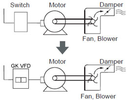 Variable Frequency Drive (VFD) can be used in lots of fields. Variable frequency drives are widely used to control the speed of ...
 Variable Frequency Drive (VFD) can be used in lots of fields. Variable frequency drives are widely used to control the speed of ...
VFD manufacturers
