VFD Carrier frequency
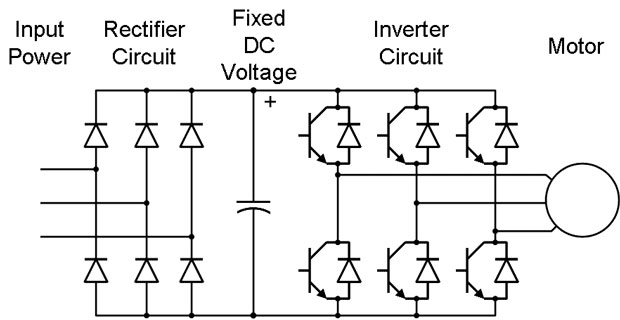
Carrier frequency is the frequency at which the output transistors are switched. In the mid 1980's when I got into the business, the power transistors were Darlingtons, fired by injecting a current on the base that was a percentage of the current carried by the collector and emitter. They could be switched only at around 1kHz or below. This made the motors "sing" - very annoying if they're running a pump or fan in an office building. There was a lot of demand for quieter motors.
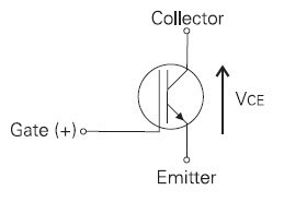
By the late 80's the Insulated Gate Bipolar Transistor (IGBT) - a high-power field-effect transistor - was brought to market. This allowed inverters to switch at 5-10kHz (though most didn't switch that fast). Faster transistor switching caused the audible noise created by the output waveform to shift up above human hearing (and/or reduced the amplitude of the motor noise by an order of magnitude or better.)
IGBT's gave multiple benefits to VFD manufacturers: Being a field-effect transistor, the circuitry required to drive the base of the transistor was made much simpler, since large currents no longer needed to be injected on the base - just a voltage. This made the variable frequency drives more efficient - less parasitic power loss, much smaller power supplies. Also, because a fault current on the output of the VFD could be interrupted much better with a field-effect transistor, overall drive reliability improved greatly. Motor torque characteristics were improved because the output waveform simulated a sine wave better. And, of course, the motors were much quieter.
Unfortunately the very fast switching characteristics of the IGBT caused other problems - namely they punched holes in motor windings. VFD reliability was great. Motor reliability, not so much. The problem was exacerbated by long lead lengths between VFD and motor.
A lot of finger-pointing went on for a couple of years until the wire manufacturers came out with "inverter duty" cable, and motor manufacturers with "inverter duty" motors that could withstand the very fast switching. To my knowledge, you cannot buy a low-voltage (690V or below) VFD today that has anything but IGBTs in its inverter section.
If you want a noisy motor, turn your VFD carrier frequency down to 1kHz or below. It'll still sing.
Post a Comment:
You may also like:
Featured Articles
What is VFD, How it works? - VFD ...
 VFD is shorted for Variable Frequency Drive (also known as AC Drives and Inverters) -- that's used to make an AC motor working in ...
 VFD is shorted for Variable Frequency Drive (also known as AC Drives and Inverters) -- that's used to make an AC motor working in ...
VFD: Insulated Gate Bipolar Transistor ...
 IGBT (insulated gate bipolar transistor) provides a high switching speed necessary for PWM VFD operation. IGBTs are capable of ...
 IGBT (insulated gate bipolar transistor) provides a high switching speed necessary for PWM VFD operation. IGBTs are capable of ...
Three phase inverters
 In the variable frequency drive rectifier paper, it explains how to go from three phase alternating current voltage to a direct ...
 In the variable frequency drive rectifier paper, it explains how to go from three phase alternating current voltage to a direct ...
Variable Frequency Drive Harmonics and ...
A discussion of the benefits of variable frequency drives often leads to a question regarding electrical harmonic distortion ...
Variable frequency drive Energy saving
 Energy can be saved in a VFD by reducing the losses in the electric motor or by reducing the energy consumption of the variable ...
 Energy can be saved in a VFD by reducing the losses in the electric motor or by reducing the energy consumption of the variable ...
VFD manufacturers
