VFD: Pulse Width Modulation (PWM)
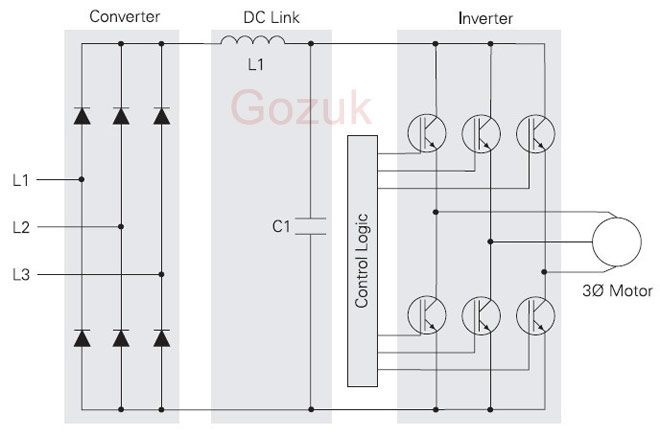
Pulse Width Modulation (PWM) VFDs provide a more sinusoidal current output to control frequency and voltage supplied to an AC motor. PWM VFDs are more efficient and typically provide higher levels of performance. A basic PWM VFD consists of a converter, DC link, control logic, and an inverter.

Converter and DC Link
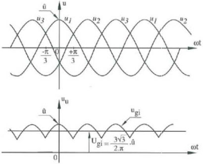
The converter section consists of a fixed diode bridge rectifier which converts the three-phase power supply to a DC voltage. The L1 choke and C1 capacitor(s) smooth the converted DC voltage. The rectified DC value is approximately 1.35 times the line-to-line value of the supply voltage. The rectified DC value is approximately 650 VDC for a 480 VAC supply.

Control Logic and Inverter
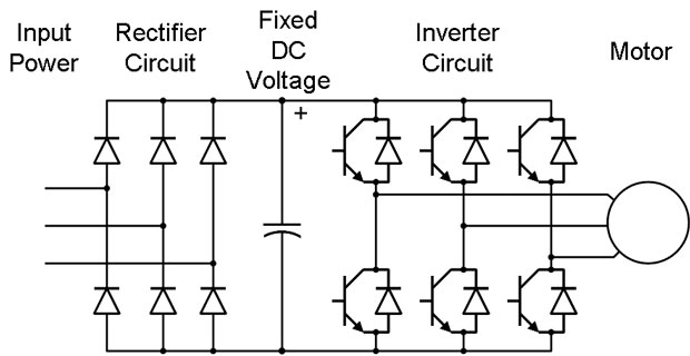
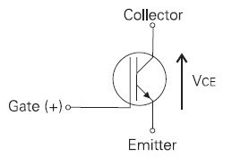
Output voltage and frequency to the motor are controlled by the control logic and inverter section. The inverter section consists of six switching devices. Various devices can be used such as thyristors, bipolar transistors, MOSFETS and IGBTs. The following schematic shows an inverter that utilizes IGBTs. The control logic uses a microprocessor to switch the IGBTs on and off providing a variable voltage and frequency to the motor.


Converter and DC Link
The converter section consists of a fixed diode bridge rectifier which converts the three-phase power supply to a DC voltage. The L1 choke and C1 capacitor(s) smooth the converted DC voltage. The rectified DC value is approximately 1.35 times the line-to-line value of the supply voltage. The rectified DC value is approximately 650 VDC for a 480 VAC supply.

Control Logic and Inverter
Output voltage and frequency to the motor are controlled by the control logic and inverter section. The inverter section consists of six switching devices. Various devices can be used such as thyristors, bipolar transistors, MOSFETS and IGBTs. The following schematic shows an inverter that utilizes IGBTs. The control logic uses a microprocessor to switch the IGBTs on and off providing a variable voltage and frequency to the motor.

This shows the basic topology of rectifier + inverter but doesn't actually go into the subject of sinusoidal PWM at all. Good stuff, misleading title?
Post a Comment:
You may also like:
Featured Articles
What is VFD, How it works? - VFD ...
 VFD is shorted for Variable Frequency Drive (also known as AC Drives and Inverters) -- that's used to make an AC motor working in ...
 VFD is shorted for Variable Frequency Drive (also known as AC Drives and Inverters) -- that's used to make an AC motor working in ...
Variable frequency drive Rectifier
 To understand variable frequency drive (VFD) better, it's necessary to explain some of the main parts of the variable frequency ...
 To understand variable frequency drive (VFD) better, it's necessary to explain some of the main parts of the variable frequency ...
VFD: Insulated Gate Bipolar Transistor ...
 IGBT (insulated gate bipolar transistor) provides a high switching speed necessary for PWM VFD operation. IGBTs are capable of ...
 IGBT (insulated gate bipolar transistor) provides a high switching speed necessary for PWM VFD operation. IGBTs are capable of ...
Three phase inverters
 In the variable frequency drive rectifier paper, it explains how to go from three phase alternating current voltage to a direct ...
 In the variable frequency drive rectifier paper, it explains how to go from three phase alternating current voltage to a direct ...
Variable Frequency Drive Harmonics and ...
A discussion of the benefits of variable frequency drives often leads to a question regarding electrical harmonic distortion ...

VFD manufacturers
