Induction motor
(This paper consists of two major parts: induction motor working principle and characteristics)
Induction motors or asynchronous motors are often called the workhorses of the industry. This is the outcome of lot of advantages of the induction motor over other technologies. The motor has a low maintenance need. The only parts that can fray are the bearings. If the induction motor isn't used excessively (to high voltage, current or mechanical impact) the bearings determine the life cycle of the induction motor.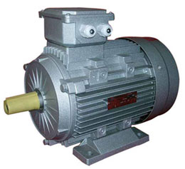 There is unlike a DC-motor no need for carbon brushes to commute the current. The induction motor can be made easily and with that the price is rather low compared with other technologies. The induction motor doesn't use a combustion process to deliver power so there is no need to (re)fuel or air. The cooling can be integrated so that the induction motor can work in a hermetically sealed environment for instance under water. The induction motor has a high power to weight ratio. Another advantage is the high start torque so that starting under load is possible. Since the development of variable frequency drives and vector control systems, this induction motor is also easy to control in speed and torque. This gave a lot of opportunities in automation processes. In the following paper, the principle, characteristics and control of the induction are explained.
Induction motor working principle
The principle of an induction motor is to make a rotating magnetic field in a stator and induce a current in a rotor so that both elements together give a power on the rotor what leads to a circular motion with certain speed and torque.
Stator
The stator is in theory a three phase winding divided over a cylindrical surface so that when a three phase voltage is applied, a rotating magnetic field is induced. The windings are bedded in a metal cylindrical structure to guide the magnetic field lines and to prevent the movement of the windings. This structure is made of laminated, punched plates. This prevents the circulation of high eddy currents in the stator. The ideal situation is a sinusoidal magnetic field but to explain the principles in the stator one winding per phase is sufficient. This is showed in following Figure.
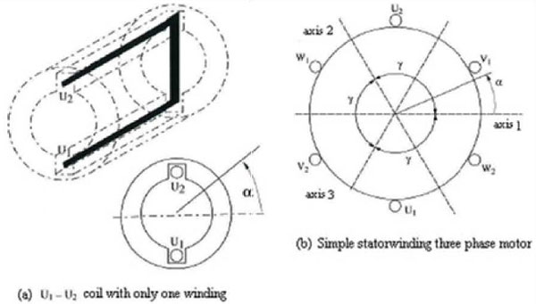
Figure 1 : Theoretical construction stator with one winding per phase
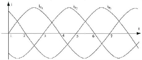
Figure 2: Three phase current is1, is2 and is3 that will be connected with coils U, V and W
Here the three windings are shifted over 120° so that it is symmetrical. The windings are often called per phase; U1 - U2, V1 - V2 and W1 - W2. In this figure there are two poles per phase. The three windings can be connected in star or delta configuration. This is often done through bridge joints outside the induction motor because dependent on the configuration the characteristics like current, voltage and direction of rotation vary.

Figure 3: Star and delta configuration with bridge joints
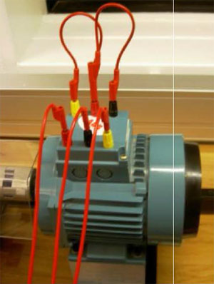
Figure 4: Induction motor in star wiring
On the three windings a three phase, symmetric, sinusoidal voltage is applied. The windings have certain admittance so that there flows a three phase, symmetric, sinusoidal current through the windings. The currents give varying magnetic fields around them. Figure 5 shows the evolution over one period of these magnetic fields.
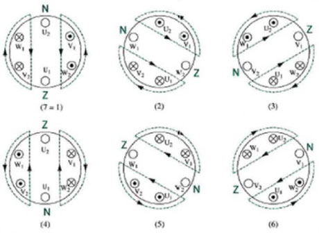
Figure 5: Magnetic situation on point of time 1 till 7 (Figure 2)
The current is positive when it flows from side 1 to side 2 (U1 - U2, V1 - V2 and W1 - W2) . The different magnetic fields per phase lead to an overall magnetic field indicated in Figure mkl. This magnetic field rotates, in this example clockwise. Every period of the voltage sine, the magnetic field makes a 360° rotation through the whole stator. If more windings per phase are placed, so that 2*p poles per phase are created, the magnetic fields makes a rotation of 360°/p per period of the voltage. If the frequency of the voltage system is fs, the frequency of the magnetic field is fs/p or the amount of revolutions per minute is
Rotor
The rotor consists of different parts. There are basically two types of rotors. Wound rotor induction motors have a rotor that contains conventional three phase windings of insulated wire. The other type that further in this paper will be used is the squirrel-cage induction motor. It has a squirrel cage rotor. For both types the rotor mantle is composed of punched laminations. They contain slits for the three phase windings or squirrel-cage. The squirrel-cage is made of metal (usually copper or aluminium) bars with at both ends a connection with a short circuit metal ring. Variations are common but the principle remains the same. The torque delivering process in the rotor is based on Faraday's law and the Lorentz force. To explain the process that happens in the rotor. Imagine a conducting ladder made of long metal sides and conducting steps like Figure 6.
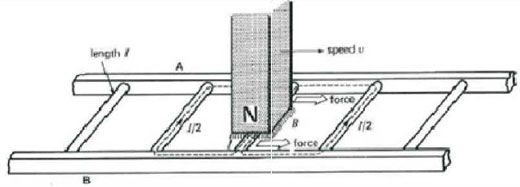
Figure 6: The ladder equivalent of the rotor
The steps have length l. Perpendicular above the plane made by the steps and the conducting side a permanent magnet is placed. Then the magnet moves parallel with the sides over the steps of the ladder without touching them. The magnet has a certain magnetic field B and velocity v according to the ladder. If this imaginary experiment is done fast enough, the several events can be noticed. Based on Faraday's law an EMF will be induced leading to a voltage over a conductor right under the magnet.
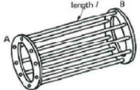
Figure 7: Squirrel cage rotor
This force acts in the same direction as the movement of the magnet because it is an induced force that counteracts its source!. If the ladder can move freely, it will start to accelerate to reduce the speed difference between ladder and magnet. When the speed difference decreases the EMF will reduce, leading to lower current, force and acceleration. If the ladder and magnet mach the same speed, the force will be zero. To make the step to the squirrel-cage induction motor, the squirrel cage rotor is equivalent to the ladder which is bent to a cylinder and the moving magnet is rep laced with the rotating magnetic field due to the three phase windings. Such cylinder is shown in Figure 7. Based on this example the principle of an induction motor is explained. Starting from the formula of the EMF in one coil the analogy can be made.
This torque is maximal when the rotor current is in phase with the stator flux. The rotor current has a big lag on the rotor EMF because of its high self inductance.
Slip
From previous chapter it is clear that the rotor never can reach the same rotational speed as the rotational magnetic field of the stator. Recapitulating: the synchronous speed of the stator flux ns depends on the frequency fs of the applied voltage and the number of pole couples p:
Rotor characteristics
Rotor frequency
The frequency of the EMF in the rotor depends on the difference between the speed of the rotor and the speed of the magnetic field in the stator:
When the rotor stood still, the difference! in speed of the rotor and the magnetic field of the stator equals the synchronous speed. In that situation the EMF Er1-rest is given by:
In the rotor flows a current due to the induced voltage. This current gives, fol lowing the Hopkinson's law, a magneto motive force. This force sets up a magnetic field that, due to the rotating character of the current system also will rotate. Earlier was shown that the frequency of the rotor voltage system fr is proportional with the frequency of the stator frequency fs with the slip factor g:
Active power flow
To understand the electrical processes in an induction motor better, it is useful to consider an equivalent circuit of the induction motor like shown in Figure 8. The galvanic separated processes of stator and rotor are hereby combined to one electric equivalent circuit of one phase. Index s indicates a stator quantity, index r a rotor quantity. The accents are used where the rotor quanti1ty is referred to the stator.
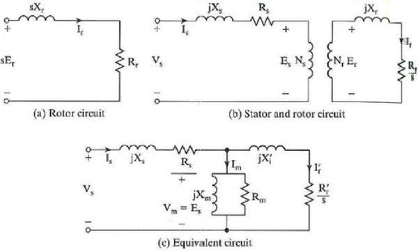
Figure 8: Equivalent circuit of an induction motor
Besides all the electric parameters of an induction motor, the basic intention is to deliver a certain torque to the shaft at a certain angular speed. With the electrical characteristic in mind, a flow diagram like showed in Figure 9 can be considered. The voltage U applied to the windings is known. In simple, non-controlled applications this is the grid voltage. In frequency controlled processes this is the voltage supplied by the variable frequency drive. The induction motor asks a certain current I. The induction motor has an inductive character because of the use of the different coils. This means that current and voltage through and over the windings are not in phase. Although it is important to know what the applied voltage is to know the impact on the isolation of the windings, the voltage is for further power derivations not so important.

Figure 9: Power flow in an induction motor
Figure 9 starts with the active applied power to the stator
Torque versus speed curve
When the torque is calculated out of the gap power Pr and the synchronous angular speed ws the next steps can be taken to find an overall expression for the torque versus speed:
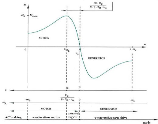
Figure 10: Torque versus speed curve of an induction motor
Figure 10 also gives an expression for the speed when the torque is maximal. Like proven before the breakdown torque is reached when the rotor speed
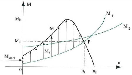
Figure 11: Graphical example of the acceleration torque
From rest a load with counteracting torque Tc1 will accelerate to point P where at every moment
This can be done outside the induction motor in the case of a wound rotor induction motor or inside the motor with the use of a double cage induction motor or higher resistance rotor bars. The wound rotor and higher resistance rotor bar principle influences directly the resistance of the rotor. The effect on the torque versus speed curve is shown in Figure 12.
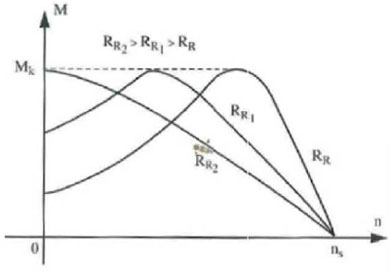
Figure 12: Torque versus speed for different rotor resistance values
The breakdown torque isn't affected like said before, only when the resistance is really high. In a wound rotor with external resistance clamps the resistance can be adjusted when the induction motor is at a higher speed to reduce the slip. In a double cage motor two squirrel cages are mounted concentric. This is shown in Figure 13. The inner cage contains thick bars and is almost completely surrounded by the iron core.
It has a high inductance and a low resistance. The outer cage is made of thinner bars that are placed close to the air gab between rotor and stator. The resistance is higher than in the inner cage. The flux around the outer bars closes its way partly in the air gab. By this it has a lower inductance. When the induction motor is started, the rotor speed wr is maximal.
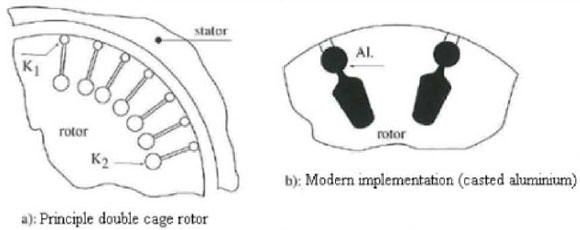
Figure 5.13: Principle double cage rotor
The reactance of the rotor is important. The rotor current will be high in the outer cage and low in the inner cage. This is the cage with the higher resistance what means a higher acceleration torque. When the induction motor gains speed, the rotor speed decreases and reaches a small value (fr ~ 1 to 4 Hz) . The reactance isn't that important anymore and the current will mainly flow in the inner cage because its resistance is much lower than the outer cage. The rotor resistance adapts fully electrical. Mainly there are three possible situations like showed in Figure 14. The first curve gives an induction motor with low rotor resistance, lower starting torque but better efficiency. The second curve illustrates the most common induction motor with an increased start torque. The third curve is called the saddle curve and is used when a really high start torque is needed, here the start torque can even be higher than the! breakdown torque.
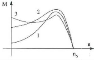
Figure 5.14: Torque courses double cage rotor
Start current
When the induction motor is started by a direct connection with the grid, a high start current will be asked from the grid. Also a high current rush will be superposed on the normal periodic sine like wave current. The grid voltage is putted over the stator while the rotor stands still. This is equivalent to the principle of a transformer with short circuited secondary coil. When the induction motor accelerates, the difference between rotor and stator decreases and the induced EMF in the rotor (secondary coil of an equivalent transformer) is reduced. Like the principle of a transformer the secondary current and by that the primary current is reduced. The ratio between start current rush and nominal current lays somewhere between 3 and 7. This is done to limit the impact on the grid and to make it easier to secure the induction motor with fuses.
Induction motors or asynchronous motors are often called the workhorses of the industry. This is the outcome of lot of advantages of the induction motor over other technologies. The motor has a low maintenance need. The only parts that can fray are the bearings. If the induction motor isn't used excessively (to high voltage, current or mechanical impact) the bearings determine the life cycle of the induction motor.
 There is unlike a DC-motor no need for carbon brushes to commute the current. The induction motor can be made easily and with that the price is rather low compared with other technologies. The induction motor doesn't use a combustion process to deliver power so there is no need to (re)fuel or air. The cooling can be integrated so that the induction motor can work in a hermetically sealed environment for instance under water. The induction motor has a high power to weight ratio. Another advantage is the high start torque so that starting under load is possible. Since the development of variable frequency drives and vector control systems, this induction motor is also easy to control in speed and torque. This gave a lot of opportunities in automation processes. In the following paper, the principle, characteristics and control of the induction are explained.
Induction motor working principle
The principle of an induction motor is to make a rotating magnetic field in a stator and induce a current in a rotor so that both elements together give a power on the rotor what leads to a circular motion with certain speed and torque.
Stator
The stator is in theory a three phase winding divided over a cylindrical surface so that when a three phase voltage is applied, a rotating magnetic field is induced. The windings are bedded in a metal cylindrical structure to guide the magnetic field lines and to prevent the movement of the windings. This structure is made of laminated, punched plates. This prevents the circulation of high eddy currents in the stator. The ideal situation is a sinusoidal magnetic field but to explain the principles in the stator one winding per phase is sufficient. This is showed in following Figure.

Figure 1 : Theoretical construction stator with one winding per phase

Figure 2: Three phase current is1, is2 and is3 that will be connected with coils U, V and W
Here the three windings are shifted over 120° so that it is symmetrical. The windings are often called per phase; U1 - U2, V1 - V2 and W1 - W2. In this figure there are two poles per phase. The three windings can be connected in star or delta configuration. This is often done through bridge joints outside the induction motor because dependent on the configuration the characteristics like current, voltage and direction of rotation vary.

Figure 3: Star and delta configuration with bridge joints

Figure 4: Induction motor in star wiring
On the three windings a three phase, symmetric, sinusoidal voltage is applied. The windings have certain admittance so that there flows a three phase, symmetric, sinusoidal current through the windings. The currents give varying magnetic fields around them. Figure 5 shows the evolution over one period of these magnetic fields.

Figure 5: Magnetic situation on point of time 1 till 7 (Figure 2)
The current is positive when it flows from side 1 to side 2 (U1 - U2, V1 - V2 and W1 - W2) . The different magnetic fields per phase lead to an overall magnetic field indicated in Figure mkl. This magnetic field rotates, in this example clockwise. Every period of the voltage sine, the magnetic field makes a 360° rotation through the whole stator. If more windings per phase are placed, so that 2*p poles per phase are created, the magnetic fields makes a rotation of 360°/p per period of the voltage. If the frequency of the voltage system is fs, the frequency of the magnetic field is fs/p or the amount of revolutions per minute is
ns = (60fs) / pLike mentioned before the previous situation of one winding per phase per pole is a simplified model. The actual distribution contains more windings per slit in the stator. Per phase this distribution is done like a sine wave. If the line from north to south according to the induced magnetic field from a phase is called the stator reference line, then the optimal distribution of Ns wires for one phase coil is given by the expression:
ns = (Ns / 2) sin αFrom this expression, according to the derivation in the magnetic induction in the air gab between stator and rotor is given by:
Bδs1 (α) = (u0Nsis1cos α) / 2δAlso from it is possible to write next formula for the effective value of the magnetic field in the air gab:
Bδ = (3Nseu0Iu) / 4δTo find the stator flux, the magnetizing inductance and induced EMF the previous formulas and the expression for the flux in one winding. So, assume one turn of coil U1 - U2. This turn makes a certain angle α with the stator reference line. Let the stator have following characteristics: radius r and axial length l. Then the flux in one turn is given by following formula:
фturn = 2 BδIr sin αFrom this expression the maximum of the whole induced flux from coil U1 - U2 can be found by integrating it over the whole distribution of windings of this phase:
The induced flux фs1 is proportional with the magnetising current Iu. This includes that flux and current are in phase. From this the magnetising inductance can be defined as:
The induced EMF in one coil is by that:
Rotor
The rotor consists of different parts. There are basically two types of rotors. Wound rotor induction motors have a rotor that contains conventional three phase windings of insulated wire. The other type that further in this paper will be used is the squirrel-cage induction motor. It has a squirrel cage rotor. For both types the rotor mantle is composed of punched laminations. They contain slits for the three phase windings or squirrel-cage. The squirrel-cage is made of metal (usually copper or aluminium) bars with at both ends a connection with a short circuit metal ring. Variations are common but the principle remains the same. The torque delivering process in the rotor is based on Faraday's law and the Lorentz force. To explain the process that happens in the rotor. Imagine a conducting ladder made of long metal sides and conducting steps like Figure 6.

Figure 6: The ladder equivalent of the rotor
The steps have length l. Perpendicular above the plane made by the steps and the conducting side a permanent magnet is placed. Then the magnet moves parallel with the sides over the steps of the ladder without touching them. The magnet has a certain magnetic field B and velocity v according to the ladder. If this imaginary experiment is done fast enough, the several events can be noticed. Based on Faraday's law an EMF will be induced leading to a voltage over a conductor right under the magnet.
E = B.l.vThis is because the conductor cuts the flux. This conductor forms together with the sides of the ladder and the nearby conducting steps a closed loop. Due to the voltage over the central step a current will flow true this loop. The direction of the voltage and current is so that the change in magnetite field is counteracted. In this example, if the magnet is moving to the right and its negative pole is above the ladder, the current will flow in the central conductor towards the front and in the nearby steps towards the back.
I = E / ZWhere Z is the impedance seen by the potential over the central conductor. Because there is a magnetic field B cutting the step and an electric current flowing through the step, a Lorentz force will act on the ladder.
F=BlI

Figure 7: Squirrel cage rotor
This force acts in the same direction as the movement of the magnet because it is an induced force that counteracts its source!. If the ladder can move freely, it will start to accelerate to reduce the speed difference between ladder and magnet. When the speed difference decreases the EMF will reduce, leading to lower current, force and acceleration. If the ladder and magnet mach the same speed, the force will be zero. To make the step to the squirrel-cage induction motor, the squirrel cage rotor is equivalent to the ladder which is bent to a cylinder and the moving magnet is rep laced with the rotating magnetic field due to the three phase windings. Such cylinder is shown in Figure 7. Based on this example the principle of an induction motor is explained. Starting from the formula of the EMF in one coil the analogy can be made.
Es1 = jwsфs1 = jwsL0IuIf the inductive and resistive voltage drop over the coil is neglected, the EMF equals the installed voltage Uc1. The rotary field induces an EMF Er1-rest in the rotor winding. When the induction motor doesn't rotate, the stator and rotor act as the primary and secondary of a transformer. Both the frequencies are equal:
fr = fsThe windings are coupled by the magnetic flux which acts as a rotary field. Like with an actual transformer, a transformation ratio can be defined for the induction motor in this not rotating situation.
k = Es1 / Er1-restThe major difference between the induction motor in this situation and an actual transformer is the zero load current. Because the much higher reluctance of the induction motor due to the air gab, the magnetizing current and by that also the zero load current are significantly higher. In an induction motor this current is 20-50% of the full load current where in an actual transformer this is only a few percents of the full load current. The Lorentz force on the rotor gives a certain torque at the shaft.
This torque is maximal when the rotor current is in phase with the stator flux. The rotor current has a big lag on the rotor EMF because of its high self inductance.
tan φ = (wLr) / RrThis is the situation where the rotor stands still for instance when the induction motor stands still. The generated torque on the rotor will cause an acceleration. As the speed of the rotor increases towards the rotational speed of the magnetic field, also cal led synchronous speed, the EMF Er1 decreases just like the rotor voltage frequency fr. If the induction motor would reach the synchronous speed, no more force will act on the rotor so this is never possible. This is why t he induction motor is also called the asynchronous motor. When the load increases, the speed decreases and the torque increases. In a loaded situation, for instance when the nominal load is applied, the speed of the induction motor is indicated by the letter n.
Induction Motor Characteristics
Slip
From previous chapter it is clear that the rotor never can reach the same rotational speed as the rotational magnetic field of the stator. Recapitulating: the synchronous speed of the stator flux ns depends on the frequency fs of the applied voltage and the number of pole couples p:
ns = (60fs) / pBecause the rotor never reaches this speed, a factor is defined to indicate the relative difference between both speeds. This factor, the slip g, is defined as follows :
g = (ns - n) / nsThe slip is often listed as a percentage. When put on a system of coordinates, the slip will have the opposite direction of the rotor speed. The slip will be zero when the rotor speed equals the synchronous speed, will be one if the induction motor stands still, will be negative during generation and will be larger than one when a rotating magnetic field is applied in the opposite direction of the rotational direction of the rotor. This is the electric braking.
Rotor characteristics
Rotor frequency
The frequency of the EMF in the rotor depends on the difference between the speed of the rotor and the speed of the magnetic field in the stator:
fr = p(ns - n) / 60 = pnsg / 60 = fsgEMF of the rotor
When the rotor stood still, the difference! in speed of the rotor and the magnetic field of the stator equals the synchronous speed. In that situation the EMF Er1-rest is given by:
E = BlvsWhen the rotor rotates at a certain speed n, the EMF which depends on the speed difference will be lower:
E = Bl(vs - vr) = gBlvsThus, when given a certain slip g the EMF in the rotor is given by:
Er = gEr1-restSpeed of the rotor magnetic field
In the rotor flows a current due to the induced voltage. This current gives, fol lowing the Hopkinson's law, a magneto motive force. This force sets up a magnetic field that, due to the rotating character of the current system also will rotate. Earlier was shown that the frequency of the rotor voltage system fr is proportional with the frequency of the stator frequency fs with the slip factor g:
fr = gfsSo the rotational speed of the rotor magnetic field wr is given by next formulas:
wr = gws = 2πfrThe rotor itself rotates with speed
w = (2πn / 60) rad / sHereby w is given by
w = (1 - g)wsSo when the rotational speed of the rotor and its field are combined the result is a rotor magnetic field that rotates with the same synchronous speed according to the stator reference line.
ws = w + wrPower and torque
Active power flow
To understand the electrical processes in an induction motor better, it is useful to consider an equivalent circuit of the induction motor like shown in Figure 8. The galvanic separated processes of stator and rotor are hereby combined to one electric equivalent circuit of one phase. Index s indicates a stator quantity, index r a rotor quantity. The accents are used where the rotor quanti1ty is referred to the stator.

Figure 8: Equivalent circuit of an induction motor
Besides all the electric parameters of an induction motor, the basic intention is to deliver a certain torque to the shaft at a certain angular speed. With the electrical characteristic in mind, a flow diagram like showed in Figure 9 can be considered. The voltage U applied to the windings is known. In simple, non-controlled applications this is the grid voltage. In frequency controlled processes this is the voltage supplied by the variable frequency drive. The induction motor asks a certain current I. The induction motor has an inductive character because of the use of the different coils. This means that current and voltage through and over the windings are not in phase. Although it is important to know what the applied voltage is to know the impact on the isolation of the windings, the voltage is for further power derivations not so important.

Figure 9: Power flow in an induction motor
Figure 9 starts with the active applied power to the stator
Pe = √3UlIl cos φ = 3UpIp cos φWhere φ is the angle between voltage and current vector in the phasor representation. Indices I and p indicate whether the used quantity is a line or phase quantity. Further the phase quantities are used because they agree with the stator quantities. From the active power that flows into the induction motor, a first part is lost in heat in the stator windings. This part, called the stator copper losses Pjs, depends on the stator resistance and current:
Pjs = 3Ip2RsAnother part is dissipated under the form of heat in the stator core. These losses are the iron losses due to the eddy currents in the core:
Pf = 3Vp2 / Rm ≈ 3Vs2 / RmThe remaining part of the power is the gap power Pr that is passed from the stator to the rotor through the air gap:
Pr = 3(Ir')2 Rs' / gFrom the gap power, a part is dissipated under the form of heat in the rotor windings, called the rotor copper losses:
Pjr = 3(Ir')2 Rs' =gRrWhat now remains is the mechanical power of the motor:
Pm = (1 - g) PrA part of the mechanical power is lost due to friction of the rotating and moving parts with air and especially stationary motor parts. This part, indicated as Pv, equals the no load power:
Pv = Pno loadFrom all this powers the overall efficiency of the induction motor can be expressed as:
η = Pout / Pin = (Pm - Pv) / (Pm + Pf + Pjs + Pfr) = Pload / PeTable 1 gives an indication of absolute and relative values of several quantities of induction motors. Small motors have a power under 11kW, big motors above 1100kW.
|
Load |
Current relative |
Torque relative |
Slip relative |
Efficiency absolute |
Power factor absolute |
|||||
|
Motor size |
Small |
Big |
Small |
Big |
Small |
Big |
Small |
Big |
Small |
Big |
|
Full load |
1 |
1 |
1 |
1 |
0.03 |
0.004 |
0.7-0.9 |
0.96-0.98 |
0.8-0.85 |
0.87-0.9 |
|
No load |
0.5 |
0.3 |
0 |
0 |
~0 |
~0 |
0 |
0 |
0.2 |
0.05 |
|
Locked rotor |
5-9 |
4-6 |
1.5-3 |
0.5-1 |
1 |
1 |
0 |
0 |
0.4 |
0.1 |
Torque versus speed curve
When the torque is calculated out of the gap power Pr and the synchronous angular speed ws the next steps can be taken to find an overall expression for the torque versus speed:
Where
Xr' = wsσr'L0is the leakage inductance of the rotor referred to the stator. From this moment on all the referred terms ...r' are replaced by terms ...R to keep the clarity. With
Us1 ≈ Es1 = φs1wsThe torque becomes:
T = (3pRR / wr) φs12 / ((RR / wr)2 + (σRL0)2)The maximum of the torque is reached when
dT / dwr = 0 (rhis happens when wr = RR / σRL0)When this is filled in the torque formula, it gives an expression of the maximum torque or breakdown torque:
T = 3pφs12 / 2σRL0A good representation of the torque versus speed curve is given in Figure 10.

Figure 10: Torque versus speed curve of an induction motor
Figure 10 also gives an expression for the speed when the torque is maximal. Like proven before the breakdown torque is reached when the rotor speed
wr = RR / σRL0The rotor speed gives the difference between the synchronous speed and the actual speed. So the breakdown torque is reached at a speed
w = ws - (1/p) RR / σRL0or given in rotations per minute RPM:
nb = ns - (30/πp) RR / σRL0The speed depends on the rotor resistance. The value of the breakdown torque itself is independent of the rotor resistance. When the speed of the rotor according to the stator reference line is higher than the synchronous speed, the value of the rotor speed wr becomes negative. The energy flow will be from the rotor to the stator. This happens when the rotor is driven or the induction machine works as generator instead of motor. A consideration that has to be made is that the torque given by the previous expressions is the gab torque so the rotor losses, friction losses and ventilation losses are not yet taken into account. In theory the induction motor can deliver the maximum torque to a load . Mostly the nominal torque is a factor 1.75-3 times smaller. This gives several effects. The nominal current will be lower, the working point will be probably far more stable, the nominal speed is almost the synchronous speed and the induction motor keeps a great acceleration torque. In Figure 11. the concept of the acceleration torque is visualized.

Figure 11: Graphical example of the acceleration torque
From rest a load with counteracting torque Tc1 will accelerate to point P where at every moment
T - Tc1 = Tα = Jmdw / dtThe actual reason of this last expression will be further explained in the chapter about mechanics. If the counteracting torque 01f the load follows course Tc2 the induction motor cannot accelerate the load on its own. To get a higher start- and acceleration torque without the use of an overrated induction motor, the solution is to have a higher rotor resistance.
This can be done outside the induction motor in the case of a wound rotor induction motor or inside the motor with the use of a double cage induction motor or higher resistance rotor bars. The wound rotor and higher resistance rotor bar principle influences directly the resistance of the rotor. The effect on the torque versus speed curve is shown in Figure 12.

Figure 12: Torque versus speed for different rotor resistance values
The breakdown torque isn't affected like said before, only when the resistance is really high. In a wound rotor with external resistance clamps the resistance can be adjusted when the induction motor is at a higher speed to reduce the slip. In a double cage motor two squirrel cages are mounted concentric. This is shown in Figure 13. The inner cage contains thick bars and is almost completely surrounded by the iron core.
It has a high inductance and a low resistance. The outer cage is made of thinner bars that are placed close to the air gab between rotor and stator. The resistance is higher than in the inner cage. The flux around the outer bars closes its way partly in the air gab. By this it has a lower inductance. When the induction motor is started, the rotor speed wr is maximal.

Figure 5.13: Principle double cage rotor
The reactance of the rotor is important. The rotor current will be high in the outer cage and low in the inner cage. This is the cage with the higher resistance what means a higher acceleration torque. When the induction motor gains speed, the rotor speed decreases and reaches a small value (fr ~ 1 to 4 Hz) . The reactance isn't that important anymore and the current will mainly flow in the inner cage because its resistance is much lower than the outer cage. The rotor resistance adapts fully electrical. Mainly there are three possible situations like showed in Figure 14. The first curve gives an induction motor with low rotor resistance, lower starting torque but better efficiency. The second curve illustrates the most common induction motor with an increased start torque. The third curve is called the saddle curve and is used when a really high start torque is needed, here the start torque can even be higher than the! breakdown torque.

Figure 5.14: Torque courses double cage rotor
Start current
When the induction motor is started by a direct connection with the grid, a high start current will be asked from the grid. Also a high current rush will be superposed on the normal periodic sine like wave current. The grid voltage is putted over the stator while the rotor stands still. This is equivalent to the principle of a transformer with short circuited secondary coil. When the induction motor accelerates, the difference between rotor and stator decreases and the induced EMF in the rotor (secondary coil of an equivalent transformer) is reduced. Like the principle of a transformer the secondary current and by that the primary current is reduced. The ratio between start current rush and nominal current lays somewhere between 3 and 7. This is done to limit the impact on the grid and to make it easier to secure the induction motor with fuses.
Post a Comment:
You may also like:
Featured Articles
Variable frequency drive Rectifier
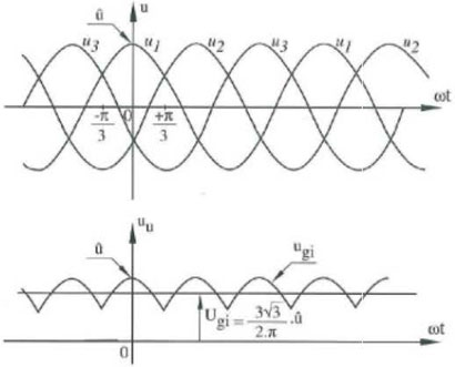 To understand variable frequency drive (VFD) better, it's necessary to explain some of the main parts of the variable frequency ...
 To understand variable frequency drive (VFD) better, it's necessary to explain some of the main parts of the variable frequency ...
VFD controlled Induction motor ...
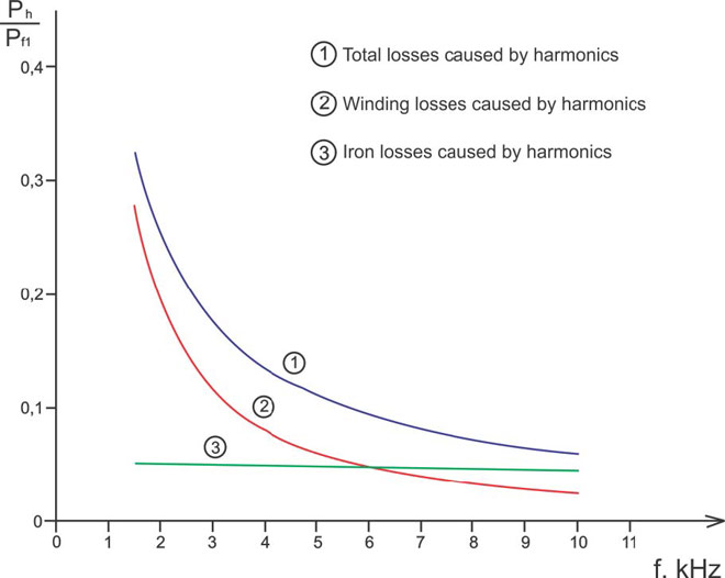 This paper presents a procedure to measure the efficiency on an induction motor fed by a VFD by the all operation range to speed ...
 This paper presents a procedure to measure the efficiency on an induction motor fed by a VFD by the all operation range to speed ...
What is VFD, How it works? - VFD ...
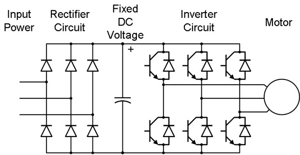 VFD is shorted for Variable Frequency Drive (also known as AC Drives and Inverters) -- that's used to make an AC motor working in ...
 VFD is shorted for Variable Frequency Drive (also known as AC Drives and Inverters) -- that's used to make an AC motor working in ...
VFD: Insulated Gate Bipolar Transistor ...
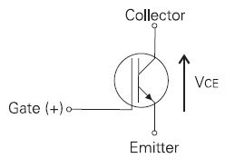 IGBT (insulated gate bipolar transistor) provides a high switching speed necessary for PWM VFD operation. IGBTs are capable of ...
 IGBT (insulated gate bipolar transistor) provides a high switching speed necessary for PWM VFD operation. IGBTs are capable of ...
VFD: Pulse Width Modulation (PWM)
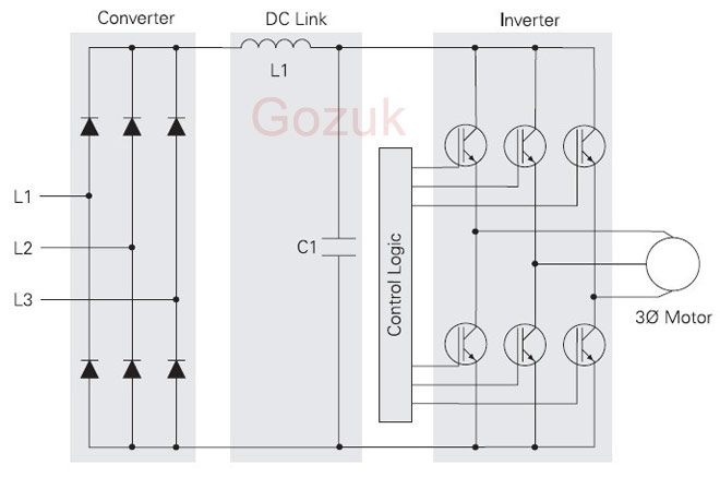 Pulse Width Modulation (PWM) VFDs provide a more sinusoidal current output to control frequency and voltage supplied to an AC ...
 Pulse Width Modulation (PWM) VFDs provide a more sinusoidal current output to control frequency and voltage supplied to an AC ...
VFD manufacturers


