Centrifugal pumps
In centrifugal pumps, it is very important for the electrical engineer to understand the pumping system variables, and the correlation between the pump curve and the hydraulic power curve of the pump, both curves are available on the pump performance curve, this understanding will allow to:
- Size the motor (usually covers the maximum power consumed by the pump plus a safety margin)
- Size the starting gear (for DOL or Star/Delta) which is usually sized based on power consumed against pump closed valve
- integrate the protection and control functions into the switchgear, those functions are divided into two categories:
1- protection against unfavorable operation variables ((e.g. long start-up time which indicate insufficient priming or closed discharge valve, over current, vibration, bearing temp etc.)
2- protection against unfavorable electrical network parameters (Under-voltage, Reverse phase, surges, etc.)
In general, if the electrical engineer does not fully understand the operation variables of the pumping operation, he will not be able to design a proper operation and protection gear.
I highly recommend that you read some literature such as Pumping station design which includes a chapter on electrical design considerations and variable frequency drive (VFD) applications. This is one of the best manuals in this domain, also many pump manufacturers have their own references for such a topic.
Generally speaking, the hydraulic power is a function of HxQ, and H is a function of Q^2, i.e. the hydraulic power is a function of Q^3, this means it is better to start the motor at a point with minimum hydraulic power demand (Q=0) to reduce the size of start gear.
Sizing of the motor itself should cover the operation point power requirements as a minimum x1.05 to 1.1 as SF. Personally I prefer to select a motor that covers the max hydraulic power over the curve (if feasible).
Post a Comment:
You may also like:
Featured Articles
Variable frequency drive Rectifier
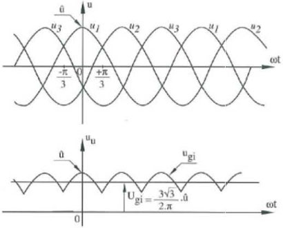 To understand variable frequency drive (VFD) better, it's necessary to explain some of the main parts of the variable frequency ...
To understand variable frequency drive (VFD) better, it's necessary to explain some of the main parts of the variable frequency ...What is VFD, How it works? - VFD ...
 VFD is shorted for Variable Frequency Drive (also known as AC Drives and Inverters) -- that's used to make an AC motor working in ...
VFD is shorted for Variable Frequency Drive (also known as AC Drives and Inverters) -- that's used to make an AC motor working in ...VFD: Insulated Gate Bipolar Transistor ...
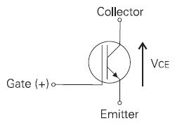 IGBT (insulated gate bipolar transistor) provides a high switching speed necessary for PWM VFD operation. IGBTs are capable of ...
IGBT (insulated gate bipolar transistor) provides a high switching speed necessary for PWM VFD operation. IGBTs are capable of ...VFD controlled Induction motor ...
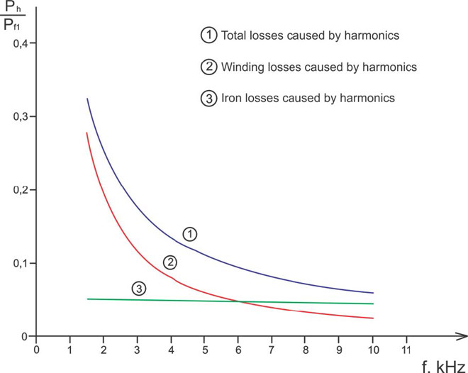 This paper presents a procedure to measure the efficiency on an induction motor fed by a VFD by the all operation range to speed ...
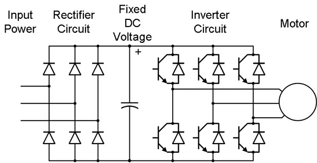
This paper presents a procedure to measure the efficiency on an induction motor fed by a VFD by the all operation range to speed ...Three phase inverters
 In the variable frequency drive rectifier paper, it explains how to go from three phase alternating current voltage to a direct ...
In the variable frequency drive rectifier paper, it explains how to go from three phase alternating current voltage to a direct ...
VFD manufacturers