Variable Frequency Drives
A Variable Frequency Drive is a motor control device that protects and controls the speed of AC induction motors. From the VFD basics theory, we know a VFD can control the speed of the motor during the start and stop cycle, as well as throughout the running cycle by outputting adjustable frequency. It also refers to as Variable Speed Drives (VSD), Adjustable Speed drive (ASD) and frequency inverter.Choose a best VFD for your electric motor and save money now:
|
|
Capacity |
Rated Current (amps) |
|
Single phase 220V - 240V 50Hz/60Hz input, three phase output. |
||
|
1 |
1HP VFD |
4.7 |
|
2 |
2HP VFD |
7.5 |
|
3 |
3HP VFD |
10 |
|
4 |
5HP VFD |
17 |
|
Three phase 380V - 440V, 50 / 60Hz input, three phase output |
||
|
5 |
7.5HP VFD |
13 |
|
6 |
10HP VFD |
17 |
|
More... |
||
How does VFD work?
Both three phase and single phase VFDs can convert input power to adjustable frequency and voltage source for controlling speed of AC induction motors. The frequency of the power applied to an AC motor determines the motor speed, based on the equation:
N = 120 x ƒ / p
where
N = speed (rpm).
f = frequency (Hz).
p = number of motor poles.
For example, a four-pole motor is operating at 60 Hz. These values can be inserted into the formula to calculate the speed:
N = 120 x 60 / 4
N = 1800 (rpm)
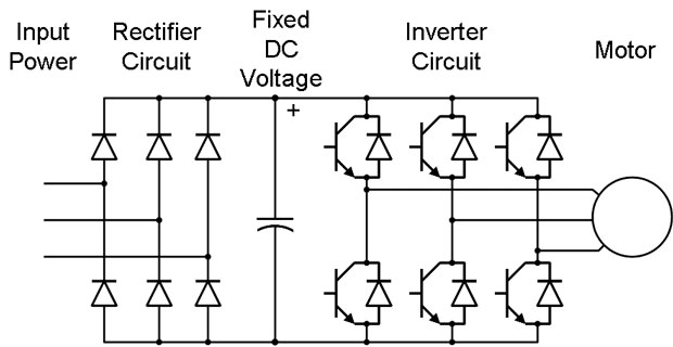
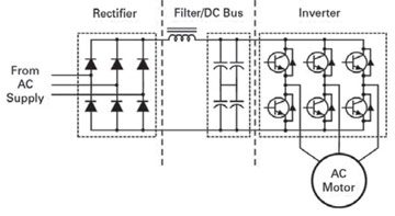
AC supply comes from the facility power network (typically 480 V, 60 Hz AC) while the rectifier converts network AC power to DC power. The filter and DC bus work together to smooth the rectified DC power and to provide clean, low-ripple DC power to the inverter (see Fig. 1: The function of a standard VFD, now there is new technology in vector VFD).
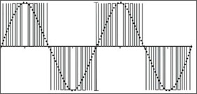
The latter uses DC power from the DC bus and filter to invert an output that resembles sine wave AC power using a pulse width modulation (PWM) technique which switches the inverter semiconductors in varying widths and times that, when averaged, create a sine waveform (see Fig. 2: A pulse-width modulated waveform).
VFD Energy savings
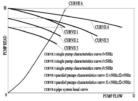
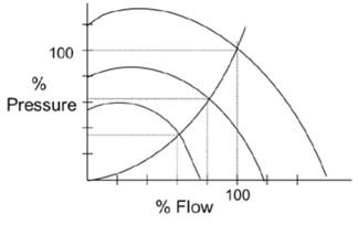
The benefits of VFDs are numerous and they offer the greatest energy savings for varies applications, the most common is VFD for pumps and fans. The adjustable flow method changes the flow curve and drastically reduces power requirements.
Centrifugal equipment such as fans, pumps, and compressors follow a general set of speed affinity laws. The affinity laws define the relationship between speed and the variables flow, pressure and power.
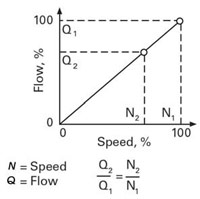
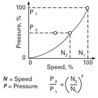
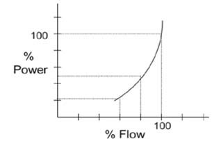
Based on the affinity laws, flow changes linearly with speed while pressure is proportional to the square of speed. The power required is proportional to the cube of the speed. The latter is most important, because if the motor speed drops, the power drops by the cube (see Figs. 3 to 5).
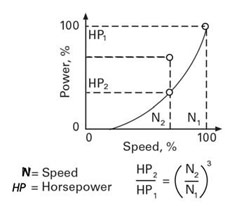
In this example, the motor is operated at 80% of the rated speed. This value can be inserted into the affinity laws formula to calculate the power at this new speed:
HP2/HP1=(N2/N1)3
(N2/N1)3=(80/100)3
=0,512
=51,2%
Therefore, the power required to operate the fan at 80% speed is half the rated power (see Figs. 6 and 7).
Ready to buy a VFD? Check out the VFD price list.
Find valuable articles, white paters and tutorials below:
The basic consideration is how close the variable frequency drive (VFD) output waveform approximates a true sinusoid. Most modern VFDs produce reasonable approximations - if viewed from a "macro" perspective. But when we zoom in to specific instances and pulses, we see there is always some amount of voltage over/undershoot occurring. And VFDs which contain an intermediate DC bus (which is pretty much a given, if the input and output are AC at different frequencies) will often have what is called a "common mode" voltage. This tends to elevate the neutral plane (on the motor side) by some amount - resulting in additional stress on the motor winding insulation.
Anything which distorts the waveform from a true sinusoid - and a true neutral - will negatively impact the insulation system through increased heating or voltage stress. Either way, the motor system has to accommodate the VFD output - so the system is designed differently.
 if viewed from a "macro" perspective. But when we zoom in to specific instances and pulses, we see there is always some amount of voltage over/undershoot occurring. And VFDs which contain an intermediate DC bus (which is pretty much a given, if the input and output are AC at different frequencies) will often have what is called a "common mode" voltage. This tends to elevate the neutral plane (on the motor side) by some amount - resulting in additional stress on the motor winding insulation.
Anything which distorts the waveform from a true sinusoid - and a true neutral - will negatively impact the insulation system through increased heating or voltage stress. Either way, the motor system has to accommodate the VFD output - so the system is designed differently.
I have delta connected capacitor banks with Auto Power Factor Controller on 440 V bus. Also motors are connected on the same bus with VFDs for starting. The question is that is there any harmful effect on the VFDs due to capacitor switching (in steps)? Does using a synchronous motor for reactive power control much better due to its smooth control?
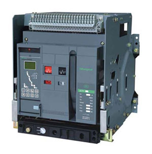 If the variable frequency drive (motor and supply cabling) is protected by fuses, we normally assume that the fuses will have sufficient interruption capacity to act as a protection device in their own right, without any additional circuit breaker.
 If the VFD is protected through a circuit breaker (mechanical contacts, controlled by some bi-metallic device, or an over-current relay), the contacts of this circuit breaker must be rated to withstand breaking of the highest current that can occur under operation of the VFD. This means, that it must typically be rated to interrupt the full short-circuit current that can occur on the busbars on the SUPPLY side of the breaker. The contact rating of this device may have to be many times the maximum possible current for the VFD itself. This value is not dependent on any rating of the VFD itself, except in the very few situations where it may have been installed at the motor end of the cable supplying the VFD. In this case, there must be some additional protection for the cable, at the supply point.
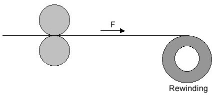
There are two ways in tension control, one way is to control the output torque of the motor, the other way is to control the motor speed. Variable frequency drive (VFD) open-loop control mode is complied with the first way, which doesn't need tension feedback. The term, "open-loop", means there is no tension feedback signal to the VFD, the VFD control the output frequency or torque to achieve the control purpose, and with no relation whether there is an encoder or not. Torque control mode means the VFD controls the motor torque instead of the frequency, the output frequency is automatically changed according to the speed.

In this paper a description is given how to set up the parameters for use the motor with a standard induction motor. Lot of this is based on the operating instructions manual that is available from Gozuk. This guide gives an explanation of how to set up the variable frequency drive (VFD) for any induction motor. The slide adaptations that are made in this setup description are because at a University the variable frequency drive is used for a specific motor and this made it possible to narrow and/or specify the original manual where the information to vague and include extra notes based on the problems that occurred during the installation of the variable frequency drive to the motor at the university. The first part of the description handles about the hardware configuration, first the fixed hardware and second the set up of the motor and control items. Where needed pictures are included to explain the process. The second part of this setup description gives a look on the different parameters in the variable frequency drive; what they mean, how to adapt them and what the possibilities are. This setting up description doesn't include actual experiments, just how the configurations are made before beginning the experiments.
Placing a proper size variable frequency drive near motor instead of in central control panels allows for much faster servicing. It also accelerates initial installations, so the system is productive sooner. Decentralized intelligence, the practice of putting motion control into VFDs instead of in central PLCs, results in simpler PLC programs that interface with smart VFDs rather than complicated programs that are large and difficult to handle.
Be sure to check application torque performance requirements (both steady state and dynamic) and select the appropriate VFD - either V/F, sensorless vector, full vector, servo, and so on. Don't forget to consider the application's environmental requirements. If a higher enclosure integrity is required (such as NEMA 12/IP55 or NEMA 4X/ IP66), some specified VFDs can provide this out of the box while others will have to be "enclosed" in a separate host enclosure to obtain these levels.
Be sure to check application torque performance requirements (both steady state and dynamic) and select the appropriate VFD - either V/F, sensorless vector, full vector, servo, and so on. Don't forget to consider the application's environmental requirements. If a higher enclosure integrity is required (such as NEMA 12/IP55 or NEMA 4X/ IP66), some specified VFDs can provide this out of the box while others will have to be "enclosed" in a separate host enclosure to obtain these levels.
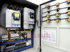 VFD panels adopt enclosed cabinet structure, generally, the protection class is IP20, IP21, IP30, and some panels may reach IP64, IP65 and even IP66 where the application environments need weatherproof, waterproof. The panels surface are coating spray by suppliers, and easy to install in parallel, the panel top configure bus and wiring the VFD keypad to the panel's door for operating directly.
Manufacturers also equip with a variety of instruments and indicators inside the variable frequency drive panels, such as voltmeter, ammeter, frequency meter, and power indicator light, alarm lights, running lights, power frequency lights etc, which will monitor the VFD control panels working status in real time.
Featured Articles
Non-Enclosure Variable Frequency Drive ...
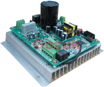 No enclosure (cover), reducing installation space and cost effective. Widely used in All-In-One control cabinet. Keep the same ...
 No enclosure (cover), reducing installation space and cost effective. Widely used in All-In-One control cabinet. Keep the same ...
Variable frequency drive application ...
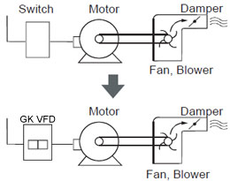 Variable Frequency Drive (VFD) can be used in lots of fields. Variable frequency drives are widely used to control the speed of ...
 Variable Frequency Drive (VFD) can be used in lots of fields. Variable frequency drives are widely used to control the speed of ...
Variable frequency drive in HVAC ...
 Variable frequency drives (VFD) have been used for HVAC systems in buildings for more than 40 years. But only in recent years, ...
 Variable frequency drives (VFD) have been used for HVAC systems in buildings for more than 40 years. But only in recent years, ...
Variable Frequency Drive Harmonics and ...
A discussion of the benefits of variable frequency drives often leads to a question regarding electrical harmonic distortion ...
Three phase inverters
 In the variable frequency drive rectifier paper, it explains how to go from three phase alternating current voltage to a direct ...
 In the variable frequency drive rectifier paper, it explains how to go from three phase alternating current voltage to a direct ...
VFD manufacturers

